Key considerations for designing fenestration systems for success
by arslan_ahmed | August 18, 2023 4:00 pm
 [1]
[1]By Bradford J. Antes, PE, and Erin E. Regan, PE
The design phase of a building project allows the design team to select fenestration systems that meet the needs of a project and set up the building for success during and after construction. Design teams must balance performance and practicality to achieve a successful installation while maintaining required fenestration performance.
This article will discuss some key items to include in the project documents during the design of a new building to help achieve a successful fenestration installation come construction.
Specifications
The first description of a new fenestration system will be in the project specifications, where there is a dedicated section describing the system, performance, and testing requirements, as well as other desired characteristics of the specific system.
Performance requirements
There is a wide range of fenestration materials available for both commercial and residential buildings, including aluminum, steel, wood, and fiberglass. The American Architectural Manufacturer’s Association (AAMA) instituted performance multiple grade standards for fenestration products in accordance with national and international building codes and other similar regulations.
Residential (R), light commercial (LC), commercial window (CW), and architectural window (AW) grades are available depending on the application, design pressure, water penetration resistance, air leakage resistance, and deflection under design loading among others. In commercial buildings,
LC, CW, and AW grades can be used depending on project performance requirements. For example, LC windows are not tested for maximum allowable deflection of unsupported spans, making them unsuitable for projects with high design loads or specific deflection criteria. It is important to note R-grade windows are intended for smaller/shorter residential buildings and single-family residences and are not appropriate for larger and taller multifamily buildings (which are classified as commercial buildings in most codes).
Laboratory testing reports should be included in the specifications as a required submittal and accompany the specified window product data. Typical testing reports have expiration, as well as retention dates that can be missed if the project team is not paying close attention. Often, contractors will submit documents for the project, including test reports that can range from four to 20 years old. Unless the manufacturer can provide written confirmation that the window’s design has not changed since the date of the test report, indicating the report is still valid to describe the performance of the windows, a recent test report (within four years) should always be provided. This ensures the system meets current test standards and procedures.
Often, designers will propose a window manufactured domestically based on aesthetics, track record, or familiarity with a certain brand. However, the contractor will sometimes propose a foreign alternate during the bid phase, often due to cost. Foreign-manufactured windows are typically tested to different standards that may not be equivalent to U.S. testing requirements.
For example, windows passing European (EN) test standards such as DIN EN 12208, Windows and Doors – Watertightness – Classification, and DIN EN 12207, Windows and Doors – Air Permeability – Classification, do not equate to passing American test standards such as ASTM E331, Standard Test Method for Water Penetration of Exterior Windows, Skylights, Doors, and Curtain Walls by Uniform Static Air Pressure Difference, or ASTM E283, Standard Test Method for Determining Rate of Air Leakage Through Exterior Windows, Skylights, Curtain Walls, and Doors under Specified Pressure Differences Across the Specimen.
If this substitution is approved, the owner will buy windows that are not the same performance as what they bought in the original design; although it is worth noting performance may end up being better in some cases.
 [2]
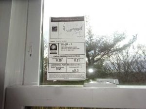
[2]The National Fenestration Rating Council (NFRC) product certification is necessary for windows to be installed in the U.S, as stated in the International Energy Conservation Code (IECC). The U-factor is a key element for new fenestration products and is listed on the product-specific NFRC label. NFRC labels list energy performance ratings for the entire fenestration product, which also can include the solar heat gain coefficient, visible light transmittance, and air leakage (Figure 1).
Code language always refers to the fenestration product U-factor, but often a center-of-glass (COG) U-factor is sometimes the only measurement submitted for a product. It is important for designers to be aware of this and the associated differences, as a COG U-factor will show much better performance than the U-factor for the entire window product, which includes window framing and other internal components. Designers should specify both values or, at minimum, the U-factor required for the entire fenestration product. As described, products tested to foreign standards for thermal performance may not be equivalent to their American counterparts and may require supplementary testing. If additional testing is required for a substitution, architects and designers can request for the product to be tested by an approved third-party laboratory. The testing should be paid for by the manufacturer or the contractor who proposed the change.
Safety glass
With some exceptions, safety glazing is required in windows as per the International Building Code (IBC) when all the following glazing conditions are met:
- Area is greater than 0.8 m2 (9 sf).
- Location is less than 457 mm (18 in.) off the floor.
- Location greater than 914 mm (36 in.) off the floor.
- Walking surface is within 914 mm (36 in.) of
the glazing.
In new buildings, especially commercial construction, there is almost always a location where safety glazing is required. Each city and state’s building code will include specific safety glass requirements in detail, typically listed under glass and glazing. There are two types of safety glass to consider: laminated glass with a dedicated interlayer, or fully tempered glass—each with its own advantages and disadvantages.
Laminated glass
Laminated glass is often chosen because should the glass break, the laminate will hold the glass in place and prevent it from falling out of the frame. Ionoplast interlayers in laminated glass are stronger and more rigid than other laminating materials, for example, polyvinyl butyral (PVB) film which is also typically used in common four-side supported vertical fenestrations in commercial construction. For ionoplast interlayers, the assembly may be stiff enough to take loading or remain vertical, such as for glass railings This is why laminated glass is required for the interior lite of skylights that are manufactured without a secondary retention screen. The laminate will prevent broken glass from falling onto occupants below.
Other benefits of laminated glass include improved acoustic performance and filtering ultraviolet (UV) radiation. However, laminated glass is usually more expensive due to the laminating process. This is where fully tempered glass becomes an attractive option for many applications as it meets safety glazing requirements.
Tempered glass
Fully tempered glazing comes with its own challenges, however. Nickel sulfide (NiS) impurities introduced into the glass during its manufacture can result in spontaneous glass fracture if it is fully tempered. NiS has a different high- and low-temperature crystalline structure; with the low-temperature form being less dense yet more stable.
During the rapid cooling process of tempering, the NiS may be locked into its relatively dense and unstable, high-temperature crystalline form. The cumulative effect of normal heating on the NiS “stone” during service (e.g. solar loads, normal diurnal temperature cycles, etc.) eventually causes it to transform into a more stable and less dense low-temperature form. When this phase of transformation takes place, the stone expands.
 [3]
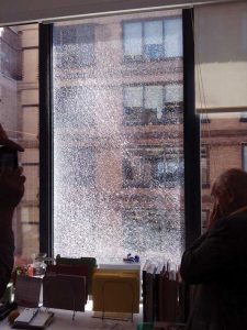
[3]If the stone is within the tension zone of the glass, this expansion, coupled with the residual tension built into the tempered glass, can cause it to spontaneously fracture and without loading or impact (Figure 2). Spontaneous breakage can occur one year or even 20 years after installation. In either case, the glass would need to be removed and replaced, usually after occupants are in the building. If fully tempered glass must be used, designers should specify mandatory heat soaking of the tempered glass at the manufacturer’s facility to minimize the risk of NiS breakage in service, although the risk cannot be eliminated. This process comes with an added cost as it involves subjecting the glass to a series of temperature changes designed to “activate” any NiS and fracture any lites that would be susceptible to spontaneous fracture in-service.
Inswing versus outswing
For punched window units, the choice between inswing or outswing windows (e.g. casement, hopper, awning, etc.) is always a discussion point. An argument can be made for both, depending on the future plans for the building. When it comes to performance, primarily leakage, outswing windows generally perform better under water penetration testing. As wind pressure is applied to the exterior of the window, it compresses the gaskets to help prevent leakage.
On the other hand, inswing windows will open slightly under negative pressure, potentially leading to leakage. If inswing windows are a project requirement due to window cleaning strategies, additional measures can be taken to ensure leakage does not reach the interior of the building, such as dedicated window flashing, larger gaskets, and tight hinges and locking mechanisms, to prevent the window from opening under negative pressure as much as possible. The adjustability of latches/keepers is also important, as compression of gaskets over time or long-term wear of hinges and other components can reduce performance. An inswing window will make window cleaning much more cost effective, as it eliminates the need for a suspended scaffold or exterior access to the facade to clean the windows.
 [4]
[4]Doors
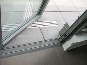
Another issue which also occurs frequently on projects is the need for doors to comply with access provisions of the Americans with Disabilities Act (ADA). This limits the swing door threshold to a maximum of 12.7 mm (0.5 in.) in height. In addition, raised thresholds and floor level changes at ADA-accessible doorways are required to be beveled with a slope no greater than 1:2 (Figure 3).
Given these restrictions, ADA-compliant doors have low water penetration resistance. If ADA compliance is required, designers should consider outswing doors to get the best possible performance against wind-driven rain. However, sometimes the project is limited to an inswing door, depending on the egress requirements or path for the space.
Currently, there are limited options for terrace doors that are rated for water penetration resistance once an ADA threshold is introduced into the assembly. As shown in Figure 3, these typically need to be installed flush or near flush with the floor on both sides, with the redundancy and drainage built into the sill frame that is set into a slab depression. While this can be an effective installation, at-grade conditions, where the threshold is essentially set directly on a concrete slab, are more difficult and may rely on water-tolerant finishes or walk-off grates/pans to manage water which will inevitably bypass the doors.
 [5]
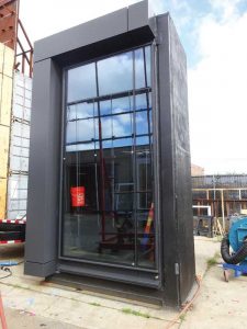
[5]Performance mockup (PMU)
The first test to be specified is a PMU test (Figure 4). This test involves constructing a mockup assembly using all components that will be installed on the building, including the fenestration system and perimeter components, and installing them according to the drawings exactly as they will be installed onsite. This is the first test of the fenestration system and its surrounding components to ensure they will work together to provide the specified performance when installed correctly.
The PMU is also an opportunity to coordinate transitions between different systems on the project and may double as a visual mockup (VMU) for the design team as well. However, the PMU is another commonly value-engineered item as it is a significant task and can lead to additional costs to coordinate the construction and necessary testing.
A PMU is especially important if a custom system is being used for the project. However, if the budget is tight or the project is relatively small, a PMU may not make sense for an off-the-shelf system with proven performance. The project schedule should also be considered when discussing a PMU. Depending on the system to be used for the project, such as a custom system, it may not be manufactured in time for a PMU.
Testing requirements
There are usually two separate paragraphs in a typical specification section describing fenestration performance. The first is lab testing, which was described earlier regarding the various AAMA ratings, and the second is in-situ testing/performance. Often, a fenestration product will easily pass a lab test, but experience failures in the field test once it is installed on the building. This can be due to installation/perimeter conditions, potential damage during installation, or even an issue during manufacturing which occurred once window production started.
Testing standard AAMA 502, Voluntary Specification for Field Testing of Newly Installed Fenestration Products allows field water tests to be conducted at two-thirds of the laboratory test pressure and states the field reduction is used to account for environmental conditions and installation. Manufacturers typically argue for field testing to include this one-third performance reduction; however, neither manufacturers nor AAMA has provided quantitative reasoning or a calculation to confirm why the performance should be reduced by one-third. Many professionals maintain the stance that a window assembly should not be damaged during installation or affected in a manner that would compromise its performance.
AAMA 502 states, unless otherwise specified and clearly stated in the project specifications, in no case shall the specified static water test pressure exceed two-thirds of the tested or rated-laboratory performance. Therefore, the specifications are the only document that can override the AAMA 502 requirement by stating no decrease in the specified test pressures will be permitted in the evaluation of field testing. Unfortunately, having this language in the specifications may not be enough to avoid arguments with manufacturers or installers during testing, both might take the stance of the one-third reduction being an “industry standard” and not up for debate.
Field testing installed fenestration units should always be included as a specification requirement. It is critical to perform a test on one of the first units installed to establish a baseline for the rest of the required testing and confirm detailing is weathertight before full installation begins. It is also important to include testing at different milestones of installation as a quality control (QC) measure to check for consistency as the project progresses.
Specifying the required test pressures for air and water penetration in the contract documents is best practice for all team members to know exactly what the designer expects on the day of the test, as is explicitly stating the passing criteria for the test. It also prevents ambiguity when it comes time to perform the test and ensures all parties are on the same page.
The specification should include the parties who must witness the field test, including, at a minimum, the designer, installer, and manufacturer. If a leak is discovered, having team members who understand the tested system and specific installation witness the test helps determine the cause and associated corrective measures and avoid ad-hoc repairs, such as adding sealant to get the system to pass.
Drawings
The drawings allow the designer to show the intent for the fenestration system and any specific detailing they want to include to help maintain the four barriers, including water, air, thermal, and vapor continuity across the building. Often, the drawings allow for a much simpler explanation than describing different fenestration components in the text within the project specifications.
An important component of the fenestration details in the drawings is showing the proposed system in the documents. This allows the detailing
to be project specific and show the basis-of-design window profile and associated anchorage, instead of using a generic window frame and anchors that will be different from what is installed on the building. This is most important for perimeter detailing and showing how the adjacent construction will tie in with the intended fenestration product. Including generic frame profiles or, worse, profiles for a different type of system (e.g. storefront versus punched windows) can lead to both performance and cost issues during construction.
Sill pan flashing
When it comes to fenestration systems, one of the most critical components to show outside of the actual system is the flashing. The flashing acts almost like part of the fenestration in terms of water management. Sill flashing is particularly important since most window leaks originate from or end up at the sill. However, flashing installation is also one of the most contested aspects of a new building. This article discusses flashing for three types of fenestration systems: punched windows, window wall systems, and curtain wall systems.
 [6]
[6]Punched windows
A stainless steel or copper, fully soldered sill pan with end dams and a back dam is essential in a fenestration system for collecting any potential leakage and directing it out of the building, especially for punched windows (Figure 5).
Unfortunately, due to the complexity of installation, the coordination required, and the additional cost for materials and installation, this sill pan flashing is often removed during the value engineering process, leaving just a few sealant joints or flat sections of sheet membrane to protect the openings. Flashing may also be changed to aluminum which relies on sealed corners at end/back dams.
While better than no metal flashing at all, sealed corners represent a common point of failure and source of leakage. It is often argued a window with a sill receptor does not require a sill pan flashing since the “receptor is designed to be watertight.” However, leakage can still occur from windowsill receptors and without a dedicated sill pan, the leakage will make its way to the interior. Common leaks through window sill receptors include not fully sealed end dams or penetrations through the sill receptor.
 [7]
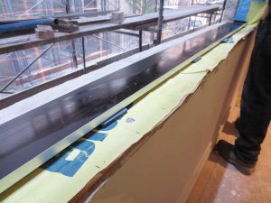
[7]Window wall
A basic detail for projects with a window wall system is a sill depression at concrete slab edges (Figure 6). This depression should be lined with waterproofing material that extends up the backside to create a pan. With this detailing, any leaks from the system are captured and cannot physically migrate to the interior due to the depression.
Typically, the depression extends several millimeters (inches) inboard of the system itself to accommodate structural attachments. When this detail is included in the final construction documents, it typically gets built as intended as it is easy to execute and does not significantly impact the cost.
In lieu of a slab depression, a sill pan could be installed below a window wall system. However, this would be impractical given the anchor penetrations through the sill pan or anchors interrupting the back dam, in addition to being more expensive than simply blocking out the slab edge during concrete placement. This makes the slab depression a much simpler method of containing potential leakage at the base of a window wall system.
 [8]
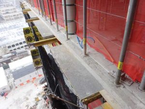
[8]Curtain wall
A common flashing detail for captured curtain wall systems is a membrane transition strip that is glazed into the glazing pocket around the perimeter of the curtain wall and laps onto the main wall waterproofing (Figure 7). This allows for the transition strip to be held in place within the glazing pocket without the need for mechanical attachment and penetrations, while maintaining a more reliable weatherproofing line than sealant joints alone. If the design team includes this detail in the documents, there is usually pushback when it comes to pricing and installing the transition strip. Most manufacturers show dual sealant joints at the interior and exterior side of the curtain wall, and an installer would rather install a sealant joint around the entire perimeter in lieu of a transition strip integrating with the fenestration.
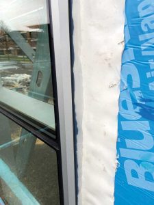
 [9]
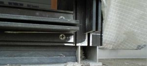
[9]A key piece of the transition membrane installation is often the need to notch or trim the screw spline at the vertical mullions to allow for continuous installation of the membrane (Figure 8). This is typically when questions or concerns come up about the flashing detail regarding potential impacts to the curtain wall warranty since it deviates from the standard manufacturer detail. With appropriate planning and some education in the field, it is straightforward to install and achieve a weathertight seal without relying on sealant alone.
Ground floor storefront
Often the ground floor storefront system is not considered a primary concern during the design phase, even though it is usually the last fenestration system installed on a building and the first one used by occupants. Although it is just a single-story system, it, too, can have challenging atypical detailing that needs to be considered during design—especially if there is no curb at the ground floor and the transition must happen at grade.
One of the main items to consider for the ground floor storefront system during design is how it integrates with the foundation waterproofing that is already installed (if present on the project). A transition membrane compatible with the below-grade waterproofing should be installed from below the storefront system to tie in with the foundation waterproofing system. In some instances, the storefront is installed on a curb, so the membrane can be installed ahead of time and still tie in properly. This transition needs to be thought through ahead of time to ensure when the storefront is installed, the foundation waterproofing is not buried, and a tie-in is possible. Typically, the top of the foundation waterproofing is damaged throughout the construction of the building, which requires repairs at the storefront tie-in location.
Not penetrating through horizontal of sill flashing
One final thought that relates to the flashing detailing is how the window system is anchored. In some window installations, the anchors go through the horizontal portion of the frame and are installed directly into the sill below. Others use clips or strap anchors fastened down to the horizontal sill just inboard of the frame. In most scenarios, if there is waterproofing and a sill pan directly below the window, the anchors or clips would penetrate both weatherproofing components, greatly reducing their effectiveness.
Anchoring the window through the upturned leg of the sill pan flashing back to a structural angle, which is then anchored into the slab or wall, avoids penetrating the horizontal surface and all the defenses installed there—if the window system can accommodate the alternate structural attachment. However, not all window manufacturers approve of this installation, and some systems may physically not allow for it, which is why getting the manufacturer on board is a key part of the process.
At a window wall system, horizontal penetrations are almost impossible to avoid, as noted previously; therefore, the penetrations must be sealed where they puncture the waterproofing membrane. However, anchorage should still be within the depression, which provides some protection against water flow to the interior. The horizontal penetrations at a curtain wall are less of a waterproofing concern if the transition membrane is glazed into the glazing pocket, as the anchorage happens further inboard of the weathering wet/dry zone plane.
Conclusion
Successful projects require careful consideration and detailing of the fenestration systems during the design phase. It is critical for clear performance requirements, testing standards, and safety glazing protocols to be outlined in the specifications for the best chance at a well-performing fenestration system. In addition, design teams should be aware of the challenges that may come along with foreign manufacturers, value engineering, and substitutions. Although cost savings may be attainable, this aspect should not come at the cost of compromised performance. Effective communication with clients and contractors is necessary to ensure projects meet the intended design goals.
Author
 Bradford J. Antes, PE, is a consulting engineer within the building technology division in the Simpson, Gumpertz & Heger Inc. (SGH) New York office. He is experienced in the design and investigation of new and existing building enclosure systems. He regularly collaborates with owners, architects, and contractors during design and construction of the building enclosure systems. He can be reached at bjantes@sgh.com.
 Erin E. Regan, PE, is a senior consulting engineer within the building technology division in the Simpson, Gumpertz & Heger Inc. (SGH) New York office. She focuses on building energy analysis, finite element analysis, roof design, window and curtain wall systems, and below-grade waterproofing. Regan has experience in design, investigation, rehabilitation, commissioning, and construction administration of historic and contemporary buildings. She can be reached at eeregan@sgh.com.
- [Image]: https://www.constructionspecifier.com/wp-content/uploads/2023/07/Opener.jpg
- [Image]: https://www.constructionspecifier.com/wp-content/uploads/2023/07/Figure-1-2.jpg
- [Image]: https://www.constructionspecifier.com/wp-content/uploads/2023/07/Figure-2-1.jpg
- [Image]: https://www.constructionspecifier.com/wp-content/uploads/2023/07/Figure-3-1.jpg
- [Image]: https://www.constructionspecifier.com/wp-content/uploads/2023/07/Figure-4.jpg
- [Image]: https://www.constructionspecifier.com/wp-content/uploads/2023/07/Figure-5.jpg
- [Image]: https://www.constructionspecifier.com/wp-content/uploads/2023/07/Figure-6-1.jpg
- [Image]: https://www.constructionspecifier.com/wp-content/uploads/2023/07/Figure-7.jpg
- [Image]: https://www.constructionspecifier.com/wp-content/uploads/2023/07/Figure-8.jpg
Source URL: https://www.constructionspecifier.com/key-considerations-for-designing-fenestration-system-for-success/