Using shear transfer at engineered wood floors
Diaphragm perimeter nailing
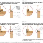
Building codes prescriptively describe the floor or roof diaphragm in conventional non-engineered construction applications. In these applications, the floor sheathing—normally wood structural panels—is attached to the floor perimeter framing with 8d 3.3 x 63-mm nails at 150 mm oc. In engineered applications, the design loads and geometry of the structure may dictate a diaphragm perimeter nailing schedule of 100 or
150 mm oc or less.
Performance of some engineered wood products, such as rim joists, can be adversely impacted by a closer nail spacing schedule. In such applications, it is important to accommodate these loads and their corresponding close nailing schedules without compromising the integrity of the rim joist.
Shear transfer of diaphragm loads to the foundation/wall framing below
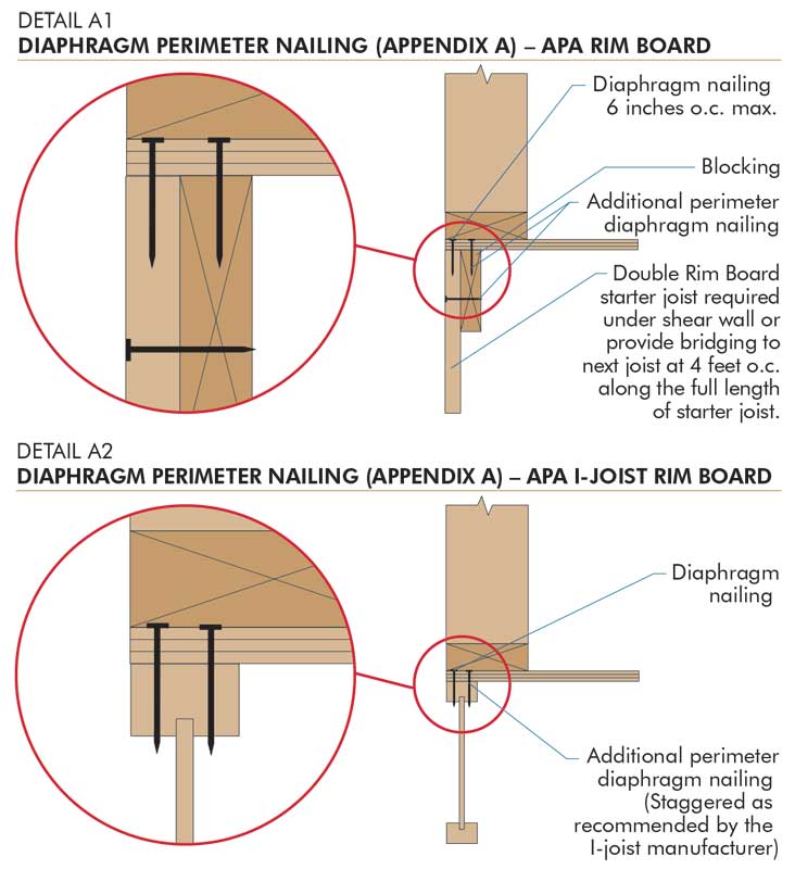
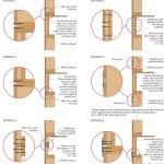
When Detail A1 or A2 is used to transfer higher diaphragm shear values into the diaphragm perimeter framing (the rim joist), the attachment schedule at the base of the framing must be adjusted to accommodate the additional load into the foundation or framing below. Minimum nailing recommendations for rim board to framing connections published in the model building codes are insufficient to transfer the additional diaphragm loads that precipitated the use of 50, 65, or 100 mm (2, 2 1⁄2, or 4 in.) oc diaphragm perimeter nailing schedules.
One should take care to prevent splitting the framing members when specifying additional fasteners. Additionally, nail and lumber specifications must provide for a minimum depth of penetration allowing full connection capacity.
Figure 1 illustrates methods that may be used in order to accommodate the project’s diaphragm perimeter nailing requirements.
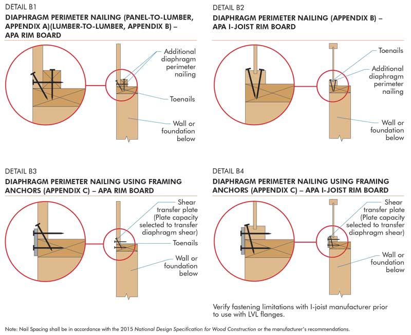
Figure 2 shows Details B1 through B4 providing examples of methods used to accommodate these loads at the base of the rim joist.
Transfer of shear wall forces from the walls above into the foundation/wall framing below
In engineered construction, lateral loads are transferred from the roof and floor diaphragms through the shear walls and eventually into the foundation. Most wood structures are now platform-framed (i.e. the interior and exterior walls sit on the floor below), and special detailing is required to transfer the forces from the shear walls above to the walls or foundation below. However, it is not always possible to transfer these forces from a shear wall above directly to the rim board below because of the possibility of splitting the framing materials forming the rim board.
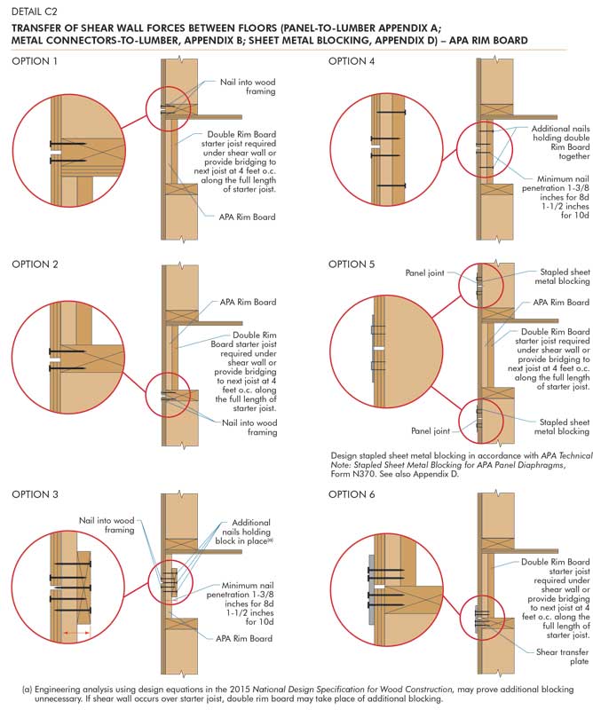
For this reason, APA–The Engineered Wood Association shows various methods to safely transfer forces around this critical connection. In Figure 3 (page 66), the details provide for all shear panel edges to occur over and be attached to common framing, subject to fastener limitations specified by the I-joist manufacturer. If connections are made at the web of the I-joist or at a rim board, one should attach backer blocking to ensure minimum nail penetration into the framing; 8d shear nailing requires 35 mm (1 3⁄8 in.) while 10d nailing requires 38 mm (1 1⁄2 in.).
Similar attachment must be provided in areas when shear-transfer nailing from the shear walls above is not accommodated by the fastener details described in C1 and C2. Detail C3 shows the transfer of shear wall forces ‘around’ the floor diaphragm to rim board connection and directly into the rim board. At the bottom of the rim board, additional nailing is required to transfer the shear wall forces into the foundation below. In C4 and C5, these shear wall forces are transferred directly into the sill plate.
Framing anchors
In addition to the direct attachment methods, framing anchors may also be used to transfer forces between the various elements of the structural frame. If it is necessary to nail into I-joist LVL flanges parallel to the gluelines when installing framing anchors, one should check with the I-joist manufacturer for nailing limitations.
Design example
An engineer is tasked with designing a two-story, platform-framed wood structure with a tile roof. Since the structure is located in an area of high seismicity (seismic design category [SDC] D2) and because of the mass of the roof, the shear walls sitting on the second floor have a design requirement of 5.55 kN/m (380 lbf/ft). The shear load along the edge of the second floor diaphragm parallel to the shear wall in question is 2.55 kN/m (175 lbf/ft) in the direction under consideration.
Since the capacity of the rim board with minimum code-required nailing is 2.63 kN/m (180 plf), no additional fastening is required or permitted at the perimeter of the diaphragm along this edge.
In the example, the engineer selected oriented strand board (OSB) from the 7⁄16 Performance Category (11-mm [7⁄16-in.]) for use as wall sheathing. No additional load can be applied to that connection because all of the capacity at the floor sheathing to rim board available to transfer the diaphragm shear has been effectively utilized. As such, the engineer uses the wall sheathing to transfer the shear wall forces ‘around’ the rim board, utilizing one of the methods shown in Detail C2, Option 4 (Figure 3).
The shear walls are attached with 8d common nails. The engineer decides to use this same size nail to transfer the shear stresses between floors:
- With 7⁄16 Performance Category OSB wall sheathing (a side member 11 mm [7⁄16 in.] thick) and a main member consisting of two layers of 28.5-mm (1 1⁄8-in.) Performance Category OSB rim board (where a penetration depth of 34 mm [1 3⁄8 in.] is required to develop the nail capacities), an unadjusted single nail has a capacity of 460 N (103 lbf) per nail.
- The number of fasteners required equals 5.55/460 x 1000 equals 12.11 fasteners per meter (3.69 per ft).
- The distance between fasteners equals 1000/12 equals 83 mm, 3.25 in. (12/3.69 equals 3.25).
- Therefore, one should use 75 mm (3 in.) oc both above and below the OSB wall sheathing joint at the double rim board.
With proper detailing, engineers and specifiers can safely and cost-effectively transfer shear loads from walls above into the foundation and walls below. (For complete details, including nailing capacities, visit www.apawood.org and download Shear Transfer at Engineered Wood Floors, Form Y2500.
Thomas D. Skaggs, PhD, PE, is the manager of product evaluation in APA–The Engineered Wood Association’s technical services division. During his 21 years at APA, he has been actively involved in dynamic testing of products, including vibration performance of I-joist floor systems and evaluating the cyclic performance of braced wall and shear wall assemblies. He was also involved in the design and implementation of APA’s full-size three-dimensional house testing program and the recent addition of combined shear and uplift testing and full-scale diaphragm testing at the APA Research Center. Prior to joining APA, Skaggs’ research at Virginia Tech was in the area of metal-plate-connected wood trusses. He can be reached at tom.skaggs@apawood.org.

