A guide to field notching and drilling LVL and glulam
This article was originally written by Borjen Yeh, PhD, PE, and published in November 2021. It has been refreshed and updated by Eric Gu, PhD, PE, to further expand on the topic of Field Notching and Drilling LVL and Glulam.
Laminated veneer lumber (LVL) and glued laminated timber (glulam) products are designed for applications where they will be highly stressed under design loads. For this reason, field modifications, such as notching, tapering or drilling, not shown on the construction documents or shop drawings, should be avoided and never done without a thorough understanding of their effects on the structural integrity of a member. Follow these guidelines if field modifications are required.
Glulam timber beams
Except for uniform-grade members, glulam beams are manufactured with lower-grade material at the mid-depth and higher-grade material at the top and bottom. The highest-grade material is used for the outermost laminations on the tension side of the beam. As a result, any drilling, dapping, or notching in these outermost tension laminations affects the beam’s strength and serviceability. First, such modifications reduce the section of the beam. Second, they remove wood fiber from the laminations with the highest strength. Stress concentrations may occur in those areas modified by notching or drilling.
Prescriptive recommendations for field notching, tapering, and drilling glulam beams follow. These recommendations assume beams are simple spans, subject to uniform loads, with the top side in compression. All equations and notching guidelines are presented using the same assumptions. If such guidance were to be applied to continuous or cantilevered beams, extreme caution shall be exercised to justify the field modifications based on rational engineering analyses. It is important to understand that improperly made field notches or holes may reduce the capacity of a properly designed member – possibly causing structural deficiency. The effects of any field notching or drilling should be checked by an engineer of record competent in timber design.
All equations and notching guidelines presented in this article use the same assumptions. If this information is applied to continuous or cantilevered beams, it should be used with extreme caution and only based on rational engineering analyses as notching or drilling continuous or cantilevered beams is more complex. It is important to understand improperly made field notches or holes may reduce the capacity of a properly designed member, possibly causing structural failure. The effects of any field notching or drilling should be checked by a designer competent in engineered timber design.
Notching
The notching of bending members should be avoided whenever possible, especially on the tension side of a member. Tension-side notching of glulam beams is not permitted except at end bearings and only under specific conditions. The notching of a bending member on the tension side results in a decrease in strength caused by stress concentrations that develop around the notch, as well as a reduction of the area resisting the bending and shear forces. Such notches induce perpendicular-to-grain tension stresses, which, in conjunction with horizontal shear forces, can cause splitting along the grain, typically starting at the inside corner of the notch. Stress concentrations due to notches can be reduced by using a gradually tapered notch configuration in lieu of a square-cornered notch. Rounding the square corner of a notch with a radius of approximately 13 mm (0.5 in.) is also recommended to reduce stress concentrations in these areas.
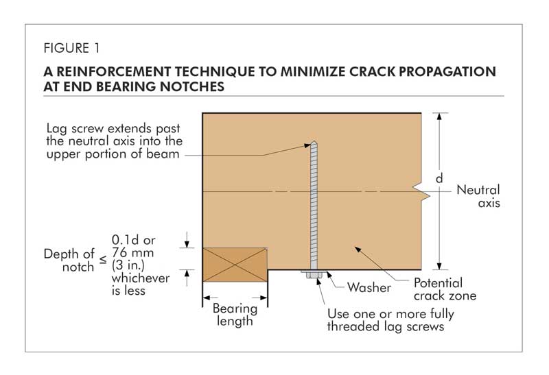
For square-cornered notches occurring at the ends of beams on the tension side, the designer may consider the use of reinforcement, such as full-threaded lag screws, to resist the tendency to split at the notch (See Figure 1). Several design methodologies exist for sizing such screws. The selected design methodology and subsequent fabrication details are the responsibility of the designer/engineer of record. If lag screws are used, lead holes shall be predrilled in accordance with accepted practice. This procedure can also be used as a field remedy to minimize further propagation of an existing crack.
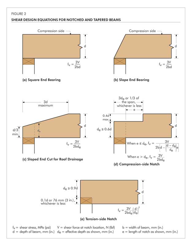
Where glulam members are notched at the ends for bearing over a support, the notch depth shall not exceed 1/10 of the beam depth. Figure 2(e) assists in evaluating the associated reductions to beam strength due to notching on the tension side. For notches on the compression side, a less severe condition exists, and equations for the analysis of the effects of these notches are also given in Figure 2. The equations given are empirical in nature and were developed for the conditions shown.
As this guideline is limited to single-span, simply supported beams, the notches shown in Figure 2 occur in areas of high shear and effectively zero moment. For this reason, the design equations given are shear equations. In situations where compression side notches extend into areas of significant moment, the bending capacity of the beam should also be checked using the remaining section of the beam and the appropriate allowable stresses for those laminations remaining at the notch location.
When it becomes necessary to cut a small notch in the top of a glulam (in the compression zone) to provide passage for small-diameter pipe or conduit, this cut should be made in areas of the beam stressed to less than 50% of the design bending stress. The net section in these areas should be checked for shear and bending stresses to ensure adequate performance.
All field notches should be accurately cut. Avoid over-cutting at the root of the notch. Drilling a pilot hole in the member at the interior corner location of a notch as a stopping point for the saw blade provides both a rounded corner and minimizes over-cutting at the corner.
Holes
Horizontal holes
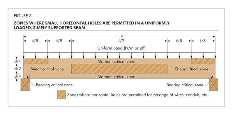
Like notches, holes in glulam remove wood fiber, thus reducing the net area of the beam at the hole location and introducing stress concentrations. These effects cause a reduction in the capacity of the beam in the penetration area. For this reason, horizontal holes in glued laminated timber are limited in size and location to maintain structural integrity. Figure 3 shows the zones of a uniformly loaded, simply supported beam where the field drilling of holes may be considered. These non-critical zones are located in portions of the beam stressed to less than 50 percent of design bending stress and less than 50 percent of design shear stress. For beams of more complex loading or other than simple spans, similar diagrams may be developed.
APA technical note, Effect of Large Diameter Horizontal Holes on the Bending and Shear Properties of Structural Glued Laminated Timber, Form V700, provides additional engineering guidelines where larger horizontal holes than those specified here cannot be avoided.
Field-drilled horizontal holes should be used for access only and not as attachment points for brackets or other load-bearing hardware unless specifically designed as such by the engineer or designer. Examples of access holes include those used for the passage of wires, electrical conduit, small-diameter sprinkler pipes, fiber-optic cables, and other small, lightweight materials. These field-drilled horizontal holes should meet the following guidelines:
1. Hole size
The hole diameter should not exceed 38 mm (1.5 in.) or one-tenth of the beam depth, whichever is smaller, with the exception of 25 mm (1 in.) diameter or smaller holes as noted in item 2 below.
2. Hole location
The hole should have a minimum clear distance, as measured from the edge of the hole to the nearest edge of the beam, of four hole diameters to the top or bottom face of the beam and eight hole diameters from the end of the beam. Note the horizontal hole should not be drilled in the moment-critical zone, as defined in Figure 3, unless approved by an engineer or architect qualified in engineered timber design.
A 25-mm (1-in.) diameter or smaller hole may be cut at the middle half of the beam depth anywhere along the span, except for the area within 152 mm (6 in.) of clear distance between the face of the support and the nearest edge of the hole (see Figure 4), provided the following conditions are all met:
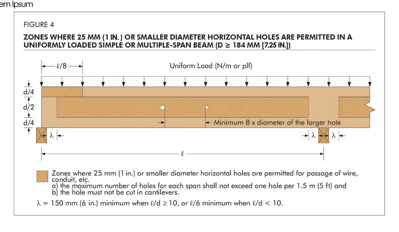
a. the beam is at least 184 mm (7.25 in.) in depth
b. the beam is subject to uniform loads only
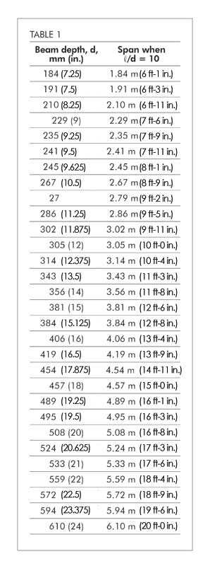
c. the span-to-depth ratio (l/d) is at least 10
d. the hole spacing and maximum number of holes must meet the requirements specified in items 3 and 4 below
e. the hole must not be cut in cantilevers
If the span-to-depth ratio of the beam is less than 10, the 25-mm (1 in.) or smaller hole may be cut in accordance with the provisions listed above, except the location of the hole must maintain a clear distance between the face of the support and the nearest edge of the hole of at least one-sixth of the span.
3. Hole spacing
The minimum clear spacing between adjacent holes, as measured between the nearest edge of the holes, should be eight hole diameters based on the largest diameter of any adjacent hole in the beam.
4. Number of holes
The maximum number of holes should not exceed one hole per 1.5 m (5 ft) of beam length. In other words, the maximum number of holes should not exceed four for a 6.1-m (20-ft) long beam. The hole spacing limitation, as given above, should be satisfied separately.
For glulam members that have been oversized, the guidelines given above may be relaxed based on an engineering analysis.
Regardless of the location, holes drilled horizontally through a member should be positioned and sized with the understanding the beam will deflect over time under in-service loading conditions. This deflection could cause distress to supported equipment or piping unless properly considered.
Vertical holes
Whenever possible, avoid drilling vertical holes through glulam beams. As a rule of thumb, vertical holes drilled through the depth of a glulam beam can reduce the capacity at that location directly proportional to the ratio of 1.5 times the diameter of the hole to the width of the beam. For example, a 25-mm (1-in.) hole drilled in a 152-mm (6-in.) wide beam would reduce the capacity of the beam at that section by approximately 25 percent ([25 x 1.5]/152).
For this reason, when it is necessary to drill vertical holes through a glulam member, the holes should be positioned in areas of the member that are stressed to less than 50 percent of design in bending. In a simply supported, uniformly loaded beam, this area would be located from the end of the beam inward approximately one-eighth of the beam span. In all cases, the minimum clear edge distance, as measured from either side of the member to the nearest edge of the vertical hole, should be 2.5 times the hole diameter. Use a drill guide to minimize “wandering” of the bit as it passes through knots or material of varying density and to ensure a true alignment of the hole through the depth of the beam.
Holes for support of suspended equipment
Heavy equipment or piping suspended from glulam beams should be attached so the load is applied to the top of members to avoid tension perpendicular-to-grain stresses. Any horizontal holes required for support of significant weight, such as suspended heating and cooling units or main water lines, must be located above the neutral axis of the member and in a zone stressed to less than 50 percent of the design flexural stress (Figure 3). Fasteners supporting light loads, such as light fixtures, must be placed at least four laminations or 25 percent of beam depth, whichever is greater, away from the tension face of the member. The design capacity of the beam should be checked for all such loads to ensure proper performance.
Laminated veneer lumber
Most LVL products are used as beams and headers loaded parallel to the gluelines. Drilling, tapering, or notching of LVL reduces the net section and may introduce stress concentrations at the notching or drilling location. Therefore, a cautious approach to field modifications is vital. Note, LVL is a proprietary product and the notching and drilling requirements specified by the LVL manufacturer must be followed and supersede the general recommendations provided hereinafter.
Notching
Notching of LVL beams should be avoided whenever possible, especially on the tension side of a member. Tension-side notching of LVL beams is not recommended except at end bearings and then only under specific conditions. The notching of LVL beams on the tension side results in decreased strength caused by stress concentrations that develop around the notch, and a reduction of the net cross-section resisting the bending and shear forces. Such notches induce perpendicular-to-grain tensile stresses, which, in conjunction with horizontal shear forces, can cause splitting along the grain, typically starting at the inside corner of the notch. Stress concentrations due to notches can be reduced by using a gradually tapered notch configuration in lieu of a square-cornered notch. Rounding the square corner of a notch with a radius of approximately 13 mm (0.5 in.) is also recommended to reduce stress concentrations in these areas.
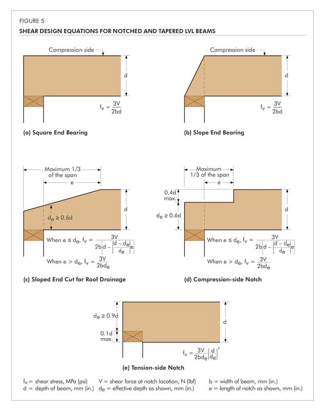
LVL beams illustrated in Figure 5 are assumed to be simple span subjected to uniform loads. All equations and notching guidelines are presented using the same assumptions. If this information is applied to continuous or cantilevered beams, it should be used with extreme caution and only based on rational engineering analyses.
Where LVL beams are notched at the ends for bearing over a support, the notch depth is recommended to not exceed one-tenth of the beam depth (Figure 5[e]). Within the limitation given above, the shear stress at the notch can be calculated in accordance with Figure 5(e). For notches on the compression side, a less severe condition exists and equations for the analysis of the effects of these notches are also given in Figure 5. The equations given are empirical in nature and were developed for the conditions shown.
The notching provisions are limited to uniformly loaded simple-span beams. The notches shown in Figure 5 occur in areas of high shear and lower moment. For this reason, the design equations given are shear equations.
When necessary to cut a small notch in the top of an LVL beam (in the compression side) to provide passage for a small-diameter pipe or conduit, the cut should be made in an area of the beam stressed to less than 50 percent of the allowable bending stress. The net section in this area of the beam should be checked for shear and bending stresses to ensure adequate performance.
All field notches should be accurately cut. It is important to understand improperly cut field notches may reduce the capacity of a beam and cause serious structural failure. Avoid over-cutting at the corners of the notch. Drilling a pilot hole in a member at the interior corner of a notch as a stop point for the saw blade provides both a rounded corner and minimizes over-cutting at the corner.
It should be recognized the top of an LVL beam might not always be stressed in compression and the bottom of an LVL beam might not always be stressed in tension. For example, if the LVL beam is designed for wind uplift, the top of the LVL will be stressed in tension and the bottom of the LVL will be stressed in compression. In this case, the recommendations given above should be applied accordingly. Further, when evaluating the effect of notching, the shear force within a distance from supports equal to the beam depth should not be neglected, as typically permitted by the design of rectangular wood members in accordance with the National Design Specification for Wood Construction (NDS) in the U.S. and the Wood Design Manual in Canada.
Holes
Horizontal holes
Like notches, holes in an LVL beam reduce the net section of the beam at the hole location and introduce stress concentrations. This causes a reduction in the beam capacity. For this reason, horizontal holes in LVL are limited in size and location to maintain the structural integrity of the beam. Figure 6 shows the zones of a uniformly loaded beam in simple or multiple spans, where the field drilling of holes may be considered. The requirements given consider the effect of the horizontal hole on the shear and moment capacities of an LVL beam and may be applied to multiple-piece built-up LVL beams.
APAtechnical note, Effect of Large Diameter Horizontal Holes on the Bending and Shear Properties of Laminated Veneer Lumber, Form V900, provides additional engineering guidelines where larger horizontal holes than those specified here cannot be avoided in design.
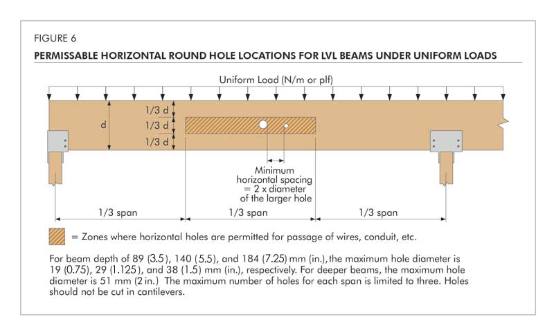
A 25-mm (1-in.) diameter or smaller hole may be cut at the middle third of the beam depth anywhere along the span, except for the area within 152 mm (6 in.) of clear distance between the face of the support and the nearest edge of the hole (Figure 7), provided the following conditions are all met:
1. the beam is at least 184 mm (7.25 in.) in depth
2. the beam is subject to uniform loads only
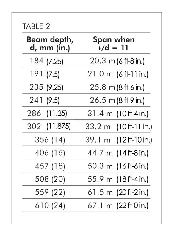
3. the span-to-depth ratio (l/d) is at least 11
4. the maximum number of holes for each span is limited to three
5. the horizontal spacing must be a minimum of two diameters clear distance between adjacent holes based on the diameter of the larger hole
6. the hole must not be cut in cantilevers
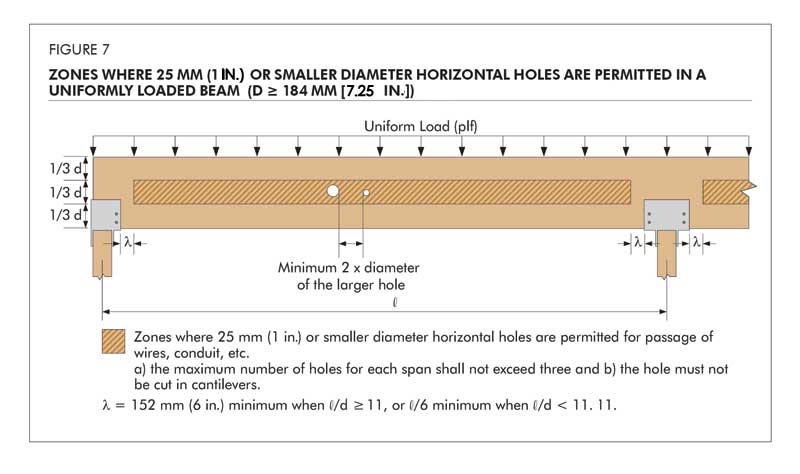
If l/d of the beam is less than 11, a 25-mm (1-in.) diameter or smaller hole may be cut in accordance with the provisions listed above, except the location of the hole must maintain a clear distance between the face of the support and the nearest edge of the hole of at least one-sixth of the span.
Field-drilled horizontal holes should be used for access only and should not be used as attachment points for brackets or other load-bearing hardware unless specifically designed as such by an engineer or designer. Examples of access holes include those used for the passage of wires, electrical conduit, small-diameter sprinkler pipes, fiber-optic cables, and other small, lightweight materials. For LVL beams that have been over-sized, the guidelines given above may be relaxed based on an engineering analysis. When holes are required to be drilled outside the allowable zones, an engineering analysis should be conducted and approved by an engineer or architect qualified in wood design.
Regardless of the hole location, holes drilled horizontally through a member should be positioned and sized with the understanding the beam will deflect (creep) more over time under in-service loading conditions. This deflection could overstress supported equipment or piping unless properly considered.
Vertical holes
Whenever possible, avoid drilling vertical holes through LVL beams unless the beam width is at least 89 mm (3.5 in.). Prior to drilling any vertical holes, an engineer or architect qualified in wood design should be consulted. Use a drill guide to minimize “wandering” of the bit as it passes through knots or material of varying density and to ensure a true alignment of the hole through the depth of the beam. The vertical hole should be centered in the beam width.
As a rule of thumb, vertical holes drilled through the depth of an LVL beam cause a reduction in the capacity at that location directly proportional to the ratio of 1.5 times the diameter of the hole to the width of the beam. For example, a 13-mm (0.5-in.) hole drilled in an 89-mm (3.5-in.) wide LVL beam would reduce the beam capacity at that section by approximately 21 percent ([13[1.5]/89).
Holes for support of suspended equipment
Heavy equipment or piping suspended from LVL beams should be attached such that the load is applied to the top of the beam to avoid inducing tension perpendicular-to-grain stresses. Any horizontal holes required to support significant weight, such as suspended heating and cooling units or main water lines, should be located above the neutral axis of the beam and in a zone stressed to less than 50 percent of the allowable bending stress. The beam capacity should be checked for all such loads to ensure proper performance.
Protection of field-cut notches and holes for LVL and glulam
Frequently, LVL and glulam beams are provided from the manufacturer with the ends sealed by a protective coating. This sealer is applied to the end grain of the LVL and glulam beams to retard the migration of moisture in and out of the beam ends during transit and jobsite storage. Field cutting a notch in the end of a beam can change the moisture-absorption characteristics of the LVL/beam at the notch location. This can result in the development of seasoning checks or localized splitting developing at the root of the notch. To minimize this possibility, all notches should be sealed immediately after cutting using a water-repellent sealer. Sealing other field-cut locations as well as field-drilled holes is also recommended. These sealers can be applied with a brush, swab, roller, or spray gun. Find additional resources for free download at www.apawood.org.
Sign up for our weekly newsletter
Architectural materials and methods delivered right to your inbox
- CSI News and Notes: CSI Foundation’s construction camp; CSI spring exam; and more
- CSI News and Notes: CSI’s credentials; CSI conference theme; and more
- To be specific – CSI supports young AECO professionals
- CSI News and Notes: CSI’s foundation scholarships, national conference, and Crosswalk
- CSI News and Notes: AI’s impact; CSI 2024 conference, and more
Products


Read the Latest Issue