Construction Dewatering: Understanding its effect on below-grade waterproofing
CSM secant pile walls
Soil-cement mix secant pile walls are built by a hollow augur injecting a mixture of native soil, cement, water, and bentonite or polymer into the unexcavated site in rows of deep overlapping cylinders prior to excavation (typically 2757 to 6894 kPa [400 to 1000 psi] compressive strength), with every other adjacent cylinder having a soldier beam inserted for lateral stabilization. At the time of excavation, the shoring walls are scraped back to approximately the plane of the inside flange of the soldier beam before the waterproofing substrate is prepared.
From a shoring engineering point of view, this type of shoring wall is considered a ‘water cut-off’ wall. Nevertheless, from a waterproofing substrate standpoint, there is commonly a need for leakage repair to prepare the waterproofing substrate. This preparation is most extensive at tiebacks to the soldier beams, cracks in the CSM material (especially at reentrant corner conditions), and steel to CSM material interfaces.
Slurry walls
Slurry walls are reinforced concrete walls formed in soil prior to excavation; once placed, they are excavated similar to CSM secant pile walls. They are constructed by excavating a deep trench segment—commonly 1.8 to 2.4 m (6 to 8 ft) long—at the perimeter of the building, supporting the trench walls with bentonite slurry, placing reinforcement into the slurry, and then placing tremie concrete into the excavation to displace the bentonite slurry. Each wall segment constructed in this sequence overlaps in an ‘overbite’ into the next adjacent segment to form a continuous wall. From a shoring and structural engineering perspective, this type of shored wall is often used both for shoring purposes and also as the final below-grade structural wall for the project. This type of wall is normally not associated with a conventional below-grade waterproofing system, especially at ‘overbite’ locations in the wall where leakage is often pronounced. Moreover, at the base of slurry wall to cast-in-place concrete slab conditions, a trench in the slab is normally necessary to collect water that leaks through the wall and wall-to-slab interface. This results in more of a below-grade ‘water management’ system than a waterproofing one.
Sheetpile walls
Sheetpile walls are formed by driving corrugated sheets of steel into the ground, where each adjacent sheet interlocks with the next and the locations of interlock are sealed. This type of shoring wall is common in marine applications. From a waterproofing substrate standpoint, a seal is required at the interlock to prepare the substrate.
Practical perspectives and observations
The efficient water management during the dewatering process is imperative to successful waterproofing installation. To better manage water, one must first recognize the possible sources of water that can enter an excavated site. These potential sources include:
- precipitation (rain and snow);
- site water (including sources such as surface runoff and from construction activities);
- groundwater; and
- perched water (water held on an impervious soil/rock layer above the water table).
On the other side of the equation, it is important to consider the ways water leaves the site, which include:
- evaporation; and
- well casings with pumps.
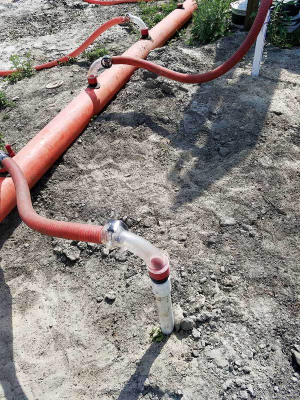
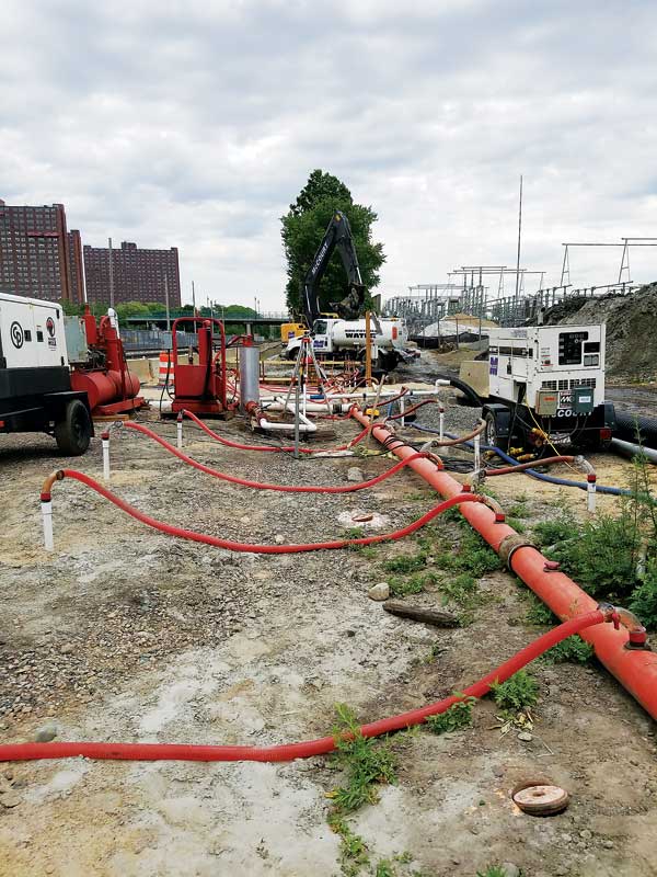
Since pumps in well casings are the main method for removing water from the excavated site, the efficient management of the water to these well casings is critical.
For the dewatering system to be effective, each step in the path must function correctly. The path moves from the below-grade soils, through filters, well casing pipes, and pumps, then into the settlement/treatment tank onsite, and finally to a point of disposal.
It is important to consider a fully functional dewatering pump may continuously draw down the water entering into the well casing, and may cause a site to be considered ‘fully dewatered.’ However, there may still be miscellaneous water on the surface of the excavation that does not reach the well casing due to the permeability of excavation top soils, or blockage of the slits in the well casing, or both without supplementary stone or media drains.
Sign up for our weekly newsletter
Architectural materials and methods delivered right to your inbox
- CSI News and Notes: CSI Foundation’s construction camp; CSI spring exam; and more
- CSI News and Notes: CSI’s credentials; CSI conference theme; and more
- To be specific – CSI supports young AECO professionals
- CSI News and Notes: CSI’s foundation scholarships, national conference, and Crosswalk
- CSI News and Notes: AI’s impact; CSI 2024 conference, and more
Products


Read the Latest Issue