Illustrating the Dew Point: An effective way to determine its value
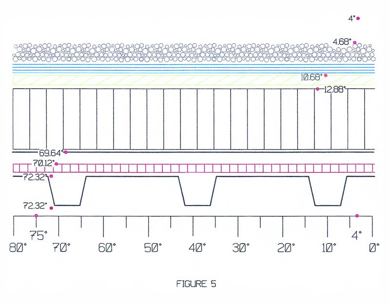
Step 6: Plot the temperature gradient values for each material onto a roof assembly drawing
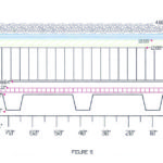
In completing this step, it is important to remember each temperature value determined in the previous step must be located at the top surface of the material layer (Figure 7).
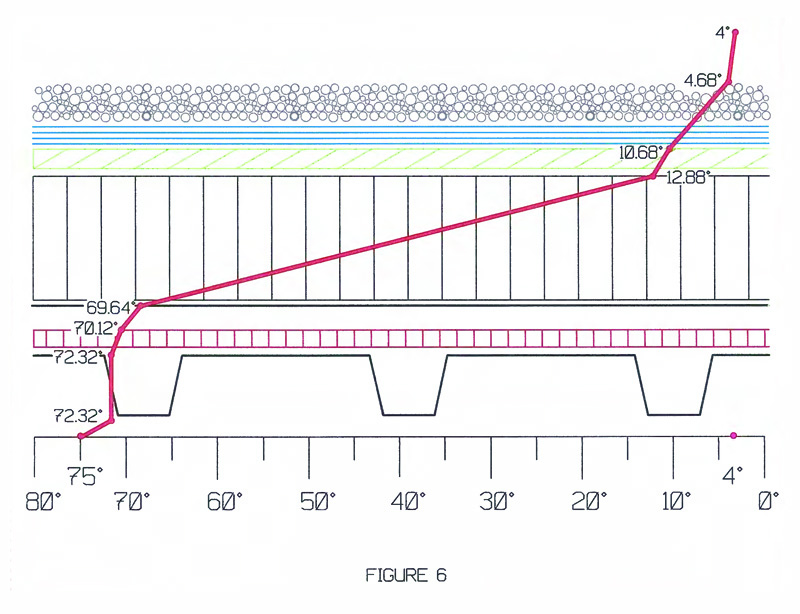
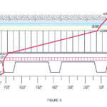
Step 7: Draw a line from the interior temperature to the next value and continue connecting the plotted temperature values until the line reaches the exterior design temperature This step is illustrated in Figure 8.
Step 8: Determine the dew point temperature
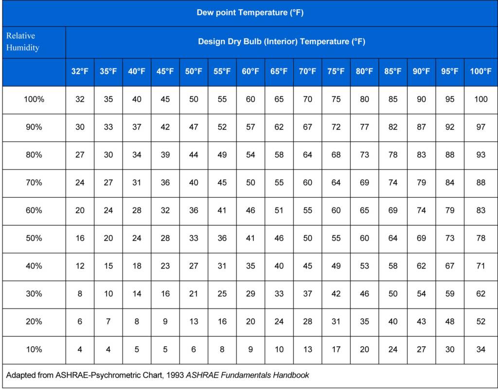
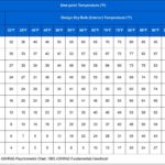
This can be determined by using a variation of the ASHRAE Psychrometric Chart shown in Figure 9. The dew point temperature occurs at the intersection of the design dry-bulb temperature column and the RH row. In this example, the dew point temperature is 49 F (i.e. 9.44 C).
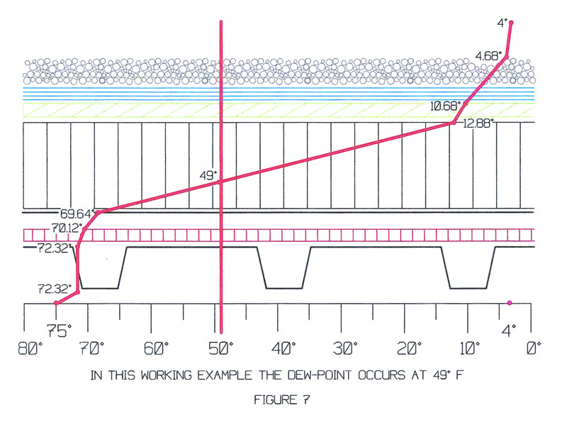
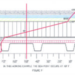
In this working example, 75 F (i.e. 22.88 C) is the dry bulb (interior) temperature and 40 F (i.e. 4 C) is specifically listed as a relative humidity, so no linear interpolation is necessary. Returning to the graphic illustration of the roof assembly, the dew point temperature value can now be plotted and located on the temperature gradient line (Figure 10)
When the dew point temperature falls within the insulation placed above the vapor retarder, condensation should not occur on the bottom of the vapor retarder. However, if the dew point falls below the insulation, additional insulation is required.
Items to consider
When additional insulation is required, a new amount of the material is selected and the steps are performed again to determine whether the dew point temperature falls within the insulation. Additionally, if the dew point temperature falls within the upper portion (around the upper one-third of the insulation), the amount of insulation may be reduced if the dew point stays within and the quantity meets building code requirements. (Again, one would go through all the steps with the new amount of insulation to ensure acceptable dew point temperature results.)
Actual RH and dew point temperature values constantly change in typical building environments as the ambient temperature and/or water vapor pressure in the air change.
An HVAC system designer typically determines design values to size the equipment for the building envelope thermal insulation and water vapor control. These design values are most often based on anticipated maximum extreme conditions.
On a related note, it is important to stagger all the insulation boards, vapor retarder substrate, and high-density coverboard a minimum of 150 mm (6 in.) in all directions during installation in order to eliminate thermal bridging.
Conclusion
Why is it necessary to develop an illustration of the dew point in graphic detail? Creating the graphic illustration explored in this article is helpful to the designer in several ways. For example:
- It can help establish whether a vapor retarder is necessary during the design phase of an above-deck insulated roof system.
- It gives the designer a visual perspective of where the temperature of the dew point falls within a visual mockup of the roof system assembly.
- Once the graphic illustration is completed, one can use the information to determine whether the design calls for either adding to or subtracting from the amount of insulation proposed for use above the vapor retarder. This aspect not only allows the designer to determine the proper position of the dew point within the roof assembly, but
it also visually affords the designer the ability to determine whether the dew point temperature falls below the warm side of the vapor retarder, thereby avoiding the potential for a catastrophic loss. - It also gives the designer the ability to evaluate whether the proposed design calls for the installation of too much insulation above the vapor retarder. This evaluation can result in a significant cost savings.
| Further discussion… |
| After this article was published in the July 2017 issue of The Construction Specifier, a reader had concerns regarding the calculation. To read the letter and see the author’s response, click here. |
Anthony Katona, CDT, is the president of Alliance Roof Consultants Inc., and has been providing professional services as a building envelope and commercial roof consultant since 1999. With construction experience spanning nearly 30 years, he has an extensive background in building envelope and commercial roof consulting, along with general contracting. Katona has served as a member of the Editorial Advisory Board of The Construction Specifier. He can be reached
at alliancerc@comcast.net.

