Understanding challenges with adhered masonry veneer
Movement joints
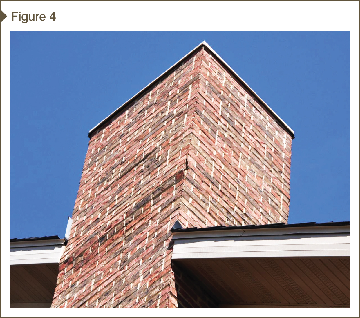
In the early years of the adhered masonry veneer market, these thin wallcoverings were primarily used for small-scale wainscot or other exterior accents on residential building types, or for interior elements such as fireplace surrounds or feature walls. Today, the adhered masonry veneer market has expanded to include whole building elevations on multi-story commercial facilities and other large buildings with increased exposure, greater loads, complex design, and high serviceability expectations. When using adhered masonry veneer systems on large-scale projects, it is critical to accommodate material and differential movement in both horizontal and vertical directions (Figure 4).
Movement joints in adhered masonry veneer systems should align with any points of expected movement in the support wall, such as:
- at or near inside and outside building corners;
- at variations of mass or height in the support wall;
- where the support wall changes material or abuts structural columns or beams;
- at sheathing expansion joints;
- where the adhered masonry veneer adjoins a dissimilar wallcovering product;
- horizontally to panelize tall elevations;
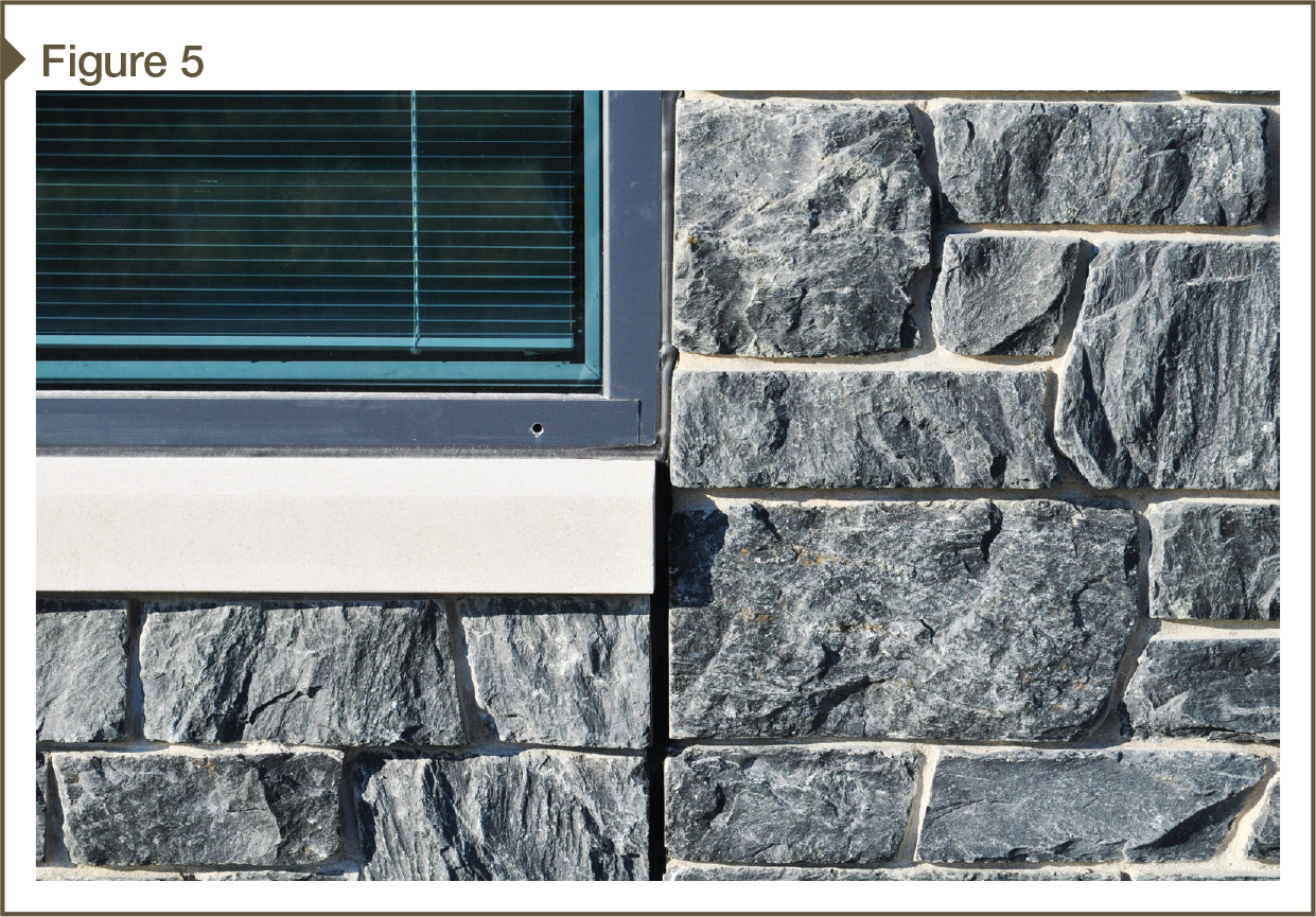
- at the perimeter of window and door openings (Figure 5); and
- at penetrations.
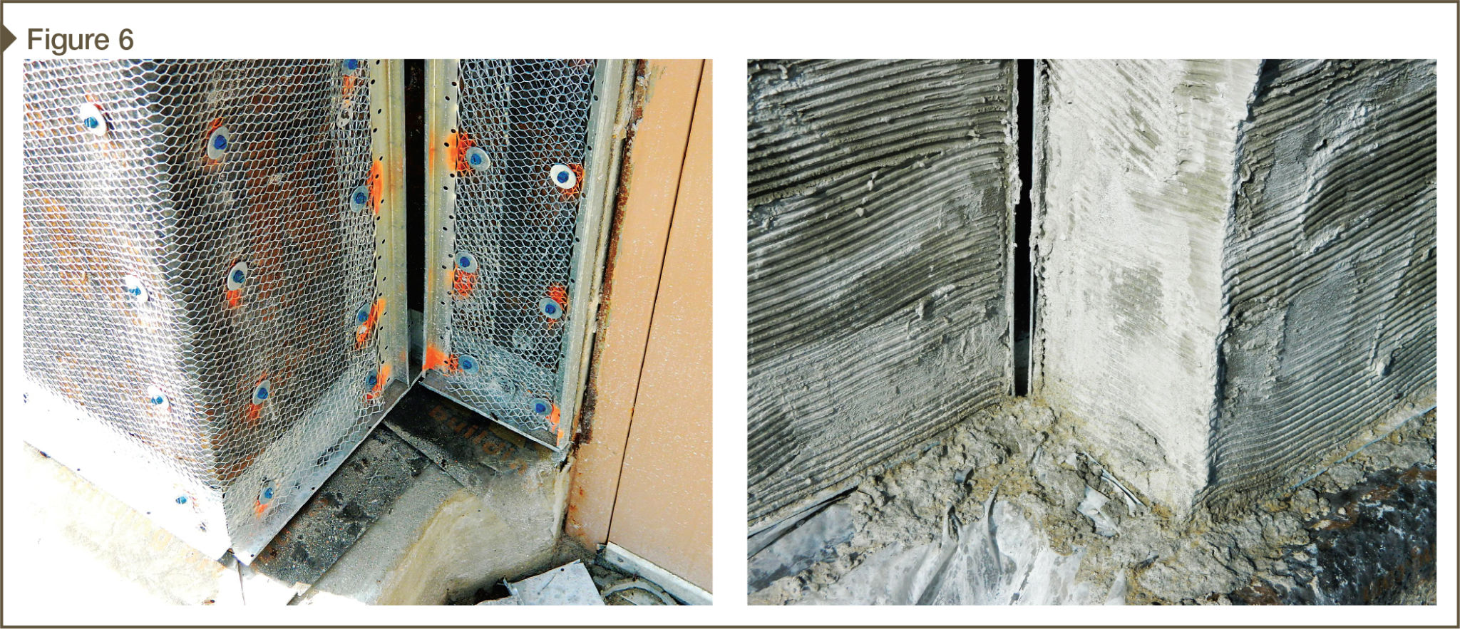
Movement joints in adhered masonry veneers are formed by using corrosion-resistant casing beads so the joint extends at least through the mortar setting bed, scratch coat, and meth lath (Figure 6). In most scenarios, the respective aligned movement joint in the support wall is made water- and airtight with an adhesive transition strip. If there is a flexible drainage mat as part of the detail, it can be continuous through the movement joint.
Like all cladding products, long vertical or horizontal expanses of masonry veneer should be panelized with movement joints to accommodate building and material movement. These joints should be spaced closer in walls with openings and in wall systems with less stiff support walls like wood or metal framed walls. Movement joints can be spaced further apart when applied over masonry support walls or in walls with no openings.
In the national masonry model code, TMS 402/ACI 530/ASCE 5, Section 6.1.6.3 requires building designers to “Design and detail the veneer to accommodate differential movement.” Additionally, the specifications component of the national masonry model code, TMS 602/ACI 530.1/ASCE 6, provides a “Mandatory Requirements Checklist,” for designers, stating in Part 3-Execution, 3.3, D.6: “Indicate type and location of movement joints on the project drawings.” In other words, it is not the mason’s responsibility to locate movement joints.
Continuous insulation
With energy codes often resulting in continuous insulation requirements on the exterior side of support walls in most climates, adhered masonry veneer systems become more complex when installed more than 13 mm (½ in.) away from the support wall. In this situation, the structural engineer-of-record needs to calculate fastener type and spacing to carry the adhered masonry veneer ‘system’ dead load back to the support wall, and account for live loads such as wind pressures. The weight of the adhered veneer system can include:
- an extra layer of sheathing on the exterior side of the insulation;
- moisture barrier;
- drainage mat;
- metal lath;
- scratch coat;
- setting mortar;
- pointing mortar; and
- veneer units.
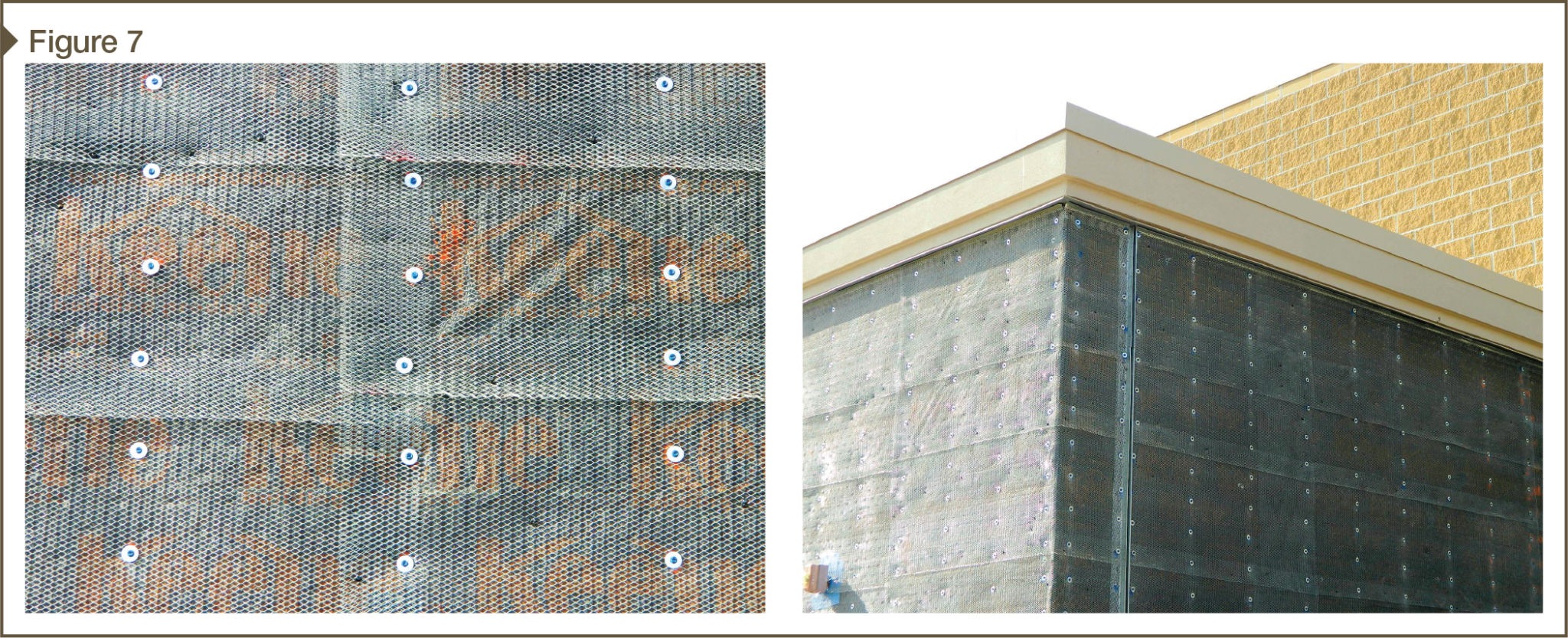
There are design guides to help designers calculate connection methods to transfer adhered veneer system loads back to the support wall. Fasteners used to secure metal lath to the building shall be fabricated in accordance with ASTM C1063-12C, Standard Specification for Installation of Lathing and Furring to Receive Interior and Exterior Portland Cement-based Plaster. One oft-overlooked requirement of this specification is the need to have fasteners with at least a 10-mm (7⁄16-in.) diameter pan wafer head to ensure proper engagement with metal lath (Figure 7).
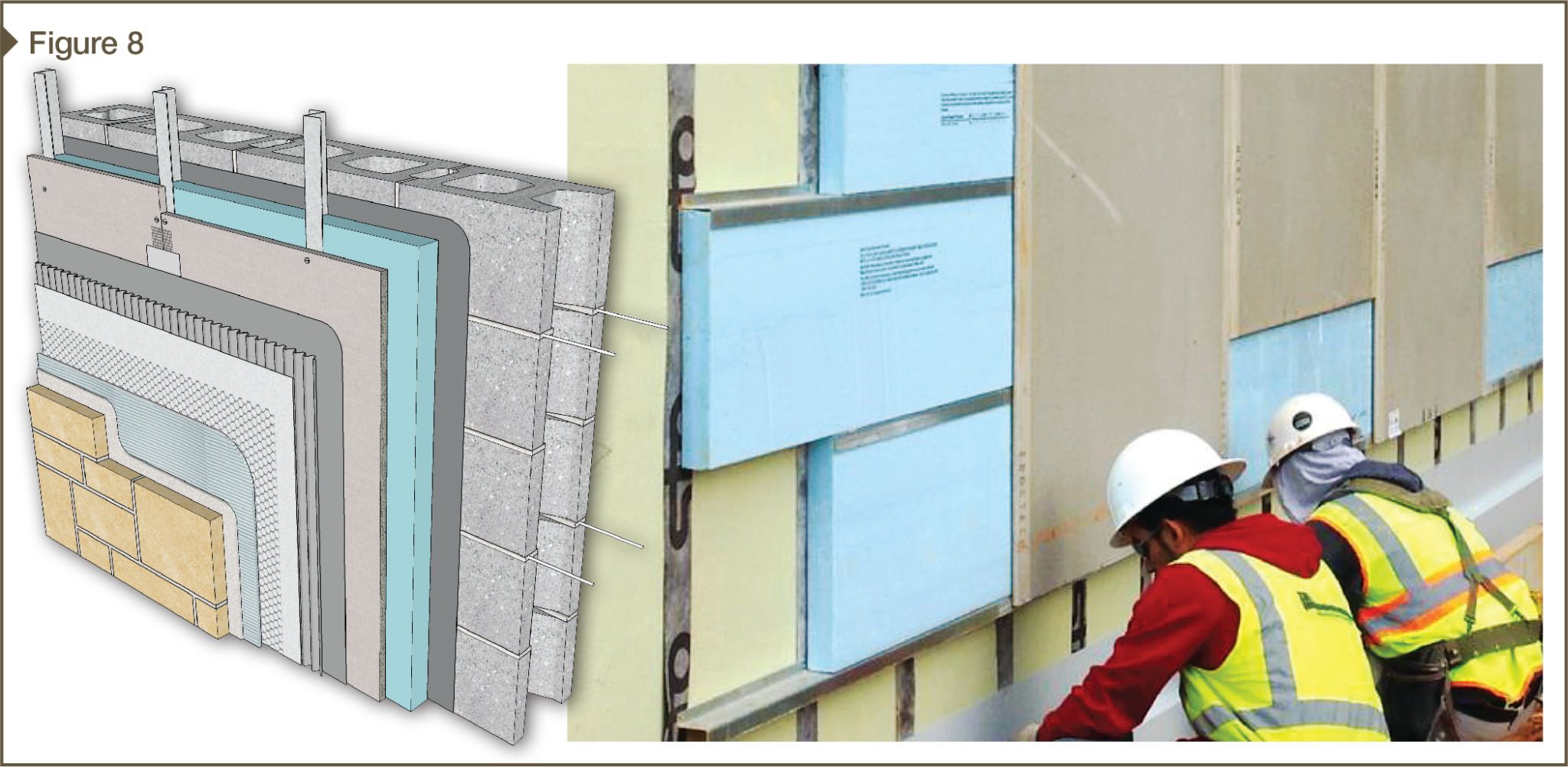
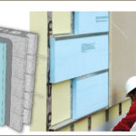
When designing adhered masonry veneer systems over continuous insulation, some of the more challenging fastener designs are when adhered veneer system loads are over insulation that is 36-mm (1 1⁄2-in.) thick or greater and the veneer system dead load is in the range of 1.2 kPa (25 psf). In these scenarios, connections back to the support wall may need to be upgraded from closely spaced heavy-gauge fasteners to continuous metal or fiberglass Z-furring channels to carry the load (Figure 8). Of course, a structural engineer should be involved to factor in all the many variables.
When Z-furring channels are mounted perpendicular to the wall framing, it is generally considered a ‘clear field anomaly’ for an acceptable ci strategy as interpreted by some energy consultants. As of the writing of this article, the impact of a wide variety of building enclosures’ thermal bridging continues to be evaluated in many exterior wall types and special conditions.

