Continuing education on continuous insulation
Continuous insulation is defined in American Society of Heating, Refrigerating, and Air-conditioning Engineers (ASHRAE) 90.1, Energy Standard for Buildings Except Low-rise Residential Buildings, as:
Insulation that is continuous across all structural members without thermal bridges other than fasteners and service openings. It is installed on the interior or exterior or is integral to any opaque surface of the building envelope.
With this in mind, different claddings will have different structural considerations, depending on ci thickness, cladding type, and the degree of energy efficiency that must be achieved to comply with building code and project requirements. In masonry wall design, brick shelf angles and lintels interfere with ci continuity which compromises energy efficiency. A recent study by Morrison-Hershfield indicates a 57 percent loss in R-value (effective R-value of 8.7 versus a nominal R-value of 20.3) caused by thermal bridging in a masonry wall assembly with substantial R-value loss attributable to a slab edge/shelf angle detail.
A more thermally efficient detail that uses intermittent brackets to hold the shelf angle out beyond the floor line to enable ci continuity improves the effective R-value from 8.7 to 9.4—this is an eight percent improvement in efficiency, but still a 54 percent loss compared to nominal R-value, despite substantially more complex and costly construction detailing. In this case, a decision has to be made whether to sacrifice energy efficiency and accept the energy loss caused by thermal bridging, or to construct a more complex and costly set of design details with improved continuity of the ci but only slight gains in energy efficiency. Alternatively, other means of mitigating thermal bridging can be explored and modeled for improvements.
Continuity of ci is more effectively achieved beneath stucco and other wall claddings attached with fasteners through ci, however, the dead load imposed by the cladding and ci on cantilevered fasteners creates a special condition that, until recently, was not fully addressed in building codes, particularly for thick (i.e. greater than 25-mm [1-in.]) insulation).
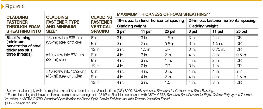
Two research projects, one sponsored by New York State Energy Research and Development Authority (NYSERDA) and another by the Foam Sheathing Coalition (FSC)—now the Foam Sheathing Committee of the American Chemistry Council (ACC)—form the basis of prescriptive attachment schedules for claddings over ci, based on cladding weight for steel framing in the 2015 IBC (Figure 5).
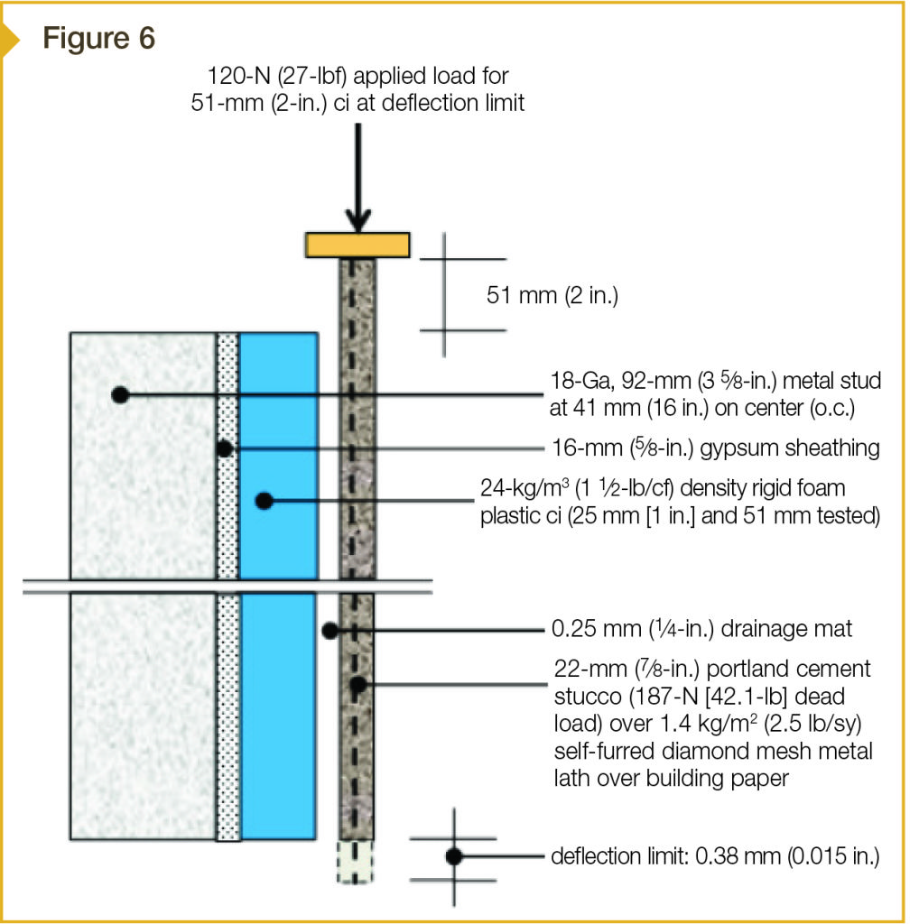
While many wall assemblies are covered by the prescriptive tables in these codes, those that do not conform to the tables require special analysis or testing to verify adequacy of fastener shear strength in relation to dead loads, and to examine the effects of long-term creep on the cladding and its attachment. Such analysis and testing was done with stucco cladding for the assembly shown in Figure 6 with 25- and 51-mm (1- and 2-in.) insulation. This assembly differs from a ‘standard’ stucco assembly with exterior ci since it incorporates a drainage mat directly behind the stucco, which adds to the cantilevered length of fastener, and potentially sets up the stucco’s rotational movement (where it is no longer restricted by a supporting solid substrate of sheathing).
Testing of the assembly was accomplished by applying loads parallel to the face of the stucco until there was a loss of load, indicating failure within the assembly. Although quite high ultimate loads were achieved (i.e. 1165 N [262 lbf] per fastener with 51-mm [2-in.] insulation), the load capacity at 0.38-mm (1⁄64-in.) deflection was the important information in the test.
NYSERDA work identified 0.38-mm maximum short-term deflection as its basis for design values and prediction of connection performance. Thus, to the extent the results of the ci stucco assembly tests mirrored the load capacity predictions of the NYSERDA work, and to the extent applied loads (above and beyond the dead load of the cladding) could be held at the deflection limit, the test validated the wall design.
Sign up for our weekly newsletter
Architectural materials and methods delivered right to your inbox
- CSI News & Notes: CSI’s impact earns official recognition; celebrate leaders, mentors, and innovators; and more
- CSI News and Notes: CSI spring certification exams open; scholarships available; and more
- CSI News & Notes: CSI MSR heading to San Diego; spring certification exams open; and more
- To Be Specific: Why CDT Should Be Your First Move
- CSI News & Notes: CSI Fellows share member benefits; and a New Year’s Resolution to keep
Related Products

Read the Latest Issue