Designing with foam plastic insulating sheathing
However, the insertion of continuous insulation creates an added dimensional thickness within the assembly previously unaccounted for in a conventional wall. This additional layer has a cascading effect on other wall components. It pushes the cladding further from the structure, which may trigger upgrades to the structural system, necessitate different wall accessories, and potentially reduce the building’s effective usable area. This is not to mention the potential impact to construction schedule associated with the additional exterior layer.
FPIS systems, which incorporate foil facers onto a polyiso board, maximize the R-value per inch relative to other foam insulations. With reported R-values of R-6.5 per inch, one would need to use 30 percent more XPS (R-5.0 per inch) or 50 percent more EPS (R-4.2 per inch for high density EPS) to construct an equivalent R-value wall assembly.
At the same time, several polyiso FPIS systems have been tested and found to meet NFPA 285 Standard Test Method for Evaluation of Fire Propagation Characteristics of Exterior Wall Assemblies Containing Combustible Components requirements as part of specified wall assemblies. Successful testing may enable a thermal barrier (typically 12.7 mm [0.5 in.] gypsum board) to be omitted from the assembly; for a metal framed building, where most climate zones require R-7.5 ci, converting the 0.5 in. of gypsum sheathing to FPIS can be the difference between prescriptive code compliance and non-compliance.
Wall assemblies featuring FPIS systems may be enhanced with cavity spray polyurethane foam (SPF). In the same efficient vein, SPF complements FPIS well. It is a highly efficient thermal insulation that also creates an effective air and vapor barrier and encapsulates the FPIS anchors, thereby minimizing thermal bridging and/or air leakage potential at board fastener penetrations.
Detailing
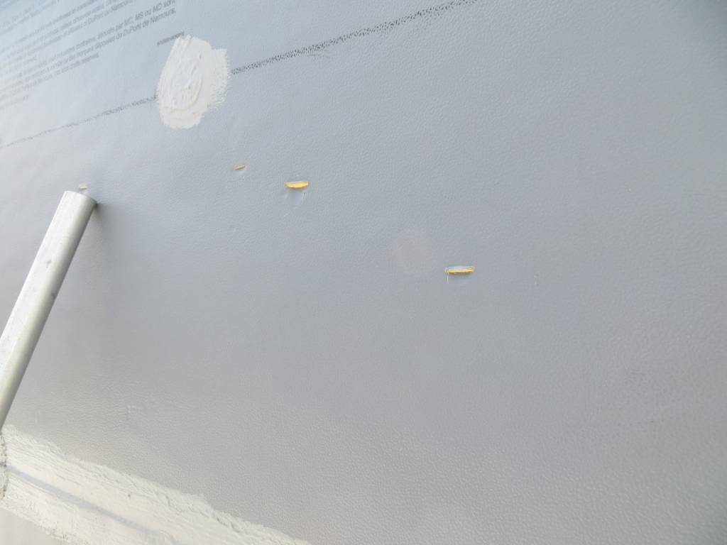
Designing with FPIS requires some deviation from conventional wall detailing. Typically, one can differentiate between the field of a wall⸺which would be covered by a continuous fluid or sheet good⸺and the edges of a wall, where the more laborious detail work occurs. FPIS installation is essentially all detail work. The field of the board is manufactured with a foil facer; the foil itself provides an air and water resistive barrier. To maintain barrier continuity, every board edge must be detailed. Any penetration through the facer creates a deficiency that must be remedied, right down to the fastener washer. Anything other than a usually solid washer requires a patch.
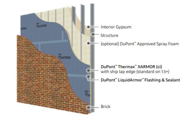
The detail work incorporates a series of accessory products to create a continuous air and weather resistive barrier along the exterior surface of FPIS. These include fluid-applied flashings, self-adhered tapes, sealants, and/or spray foams, among other products. Figure 3 illustrates one manufacturer’s basic FPIS wall assembly, with a trowel-applied fluid over all board joints.
In general, the application methods for most FPIS systems are similar, with minor component-specific variations, such as the required fluid coating edge distances (e.g. 1 in. minimum onto pipe penetrations). Tape flashing products universally require a wider application than fluid flashings. Accessory products, including masonry veneer ties, are not incidental components, but rather coordinated components as part of an integrated assembly.
There are a few differences from one system to another for designers to be aware of. While many systems include both a fluid and tape accessory to provide flexibility, some manufacturers do not incorporate a tape flashing in their accessory line or allow for perimeter sealant application (i.e. at window openings) to occur over their fluid membrane at a cut edge. As a result, the system requires additional metal trim at the entire perimeter for every rough opening.
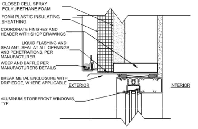
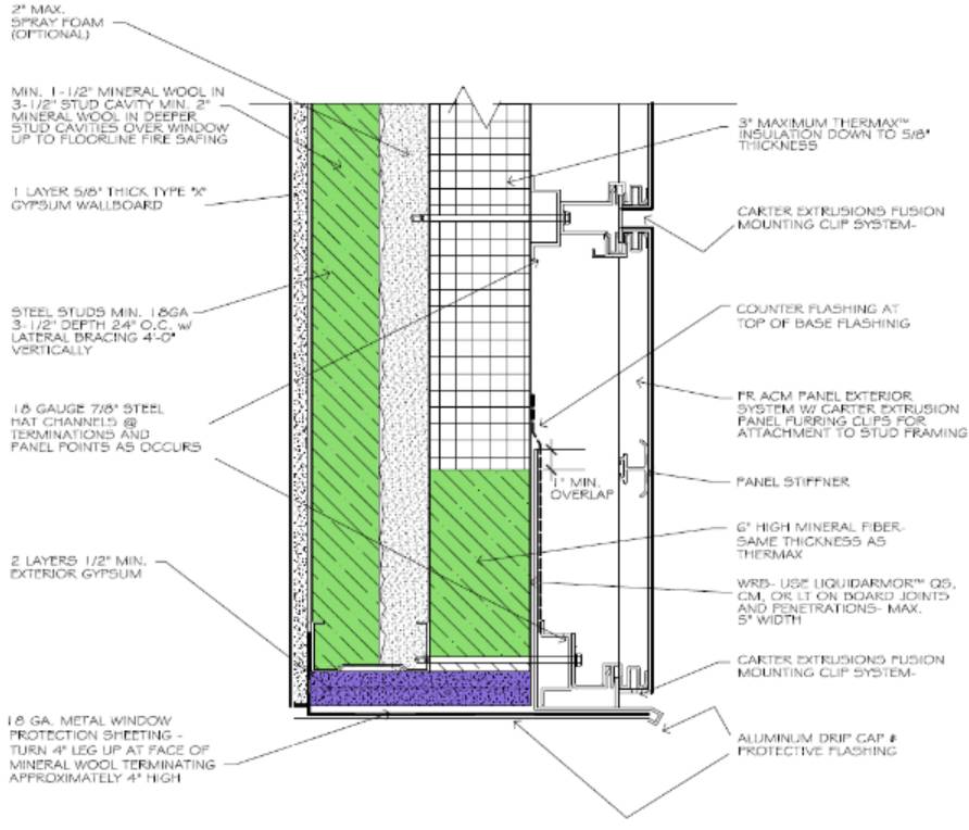
Additionally, certain systems will require special detailing at the fenestration head (e.g. mineral wool at a box beam) and/or fire-resistive treated wood blocking. This is especially critical where SPF is introduced into the system and there is a requirement to protect the SPF from exposure at the fenestration.
Applications
In terms of code requirements, the potential building applications are nearly limitless. That said, some applications are better than others, often those which capitalize on the efficiency of FPIS. Building designs featuring a low window wall ratio (WWR) derive more value from FPIS systems than higher WWR designs such as data centers, cold storage buildings, and other industrial facilities. This is not meant to imply FPIS systems cannot be utilized for commercial, daylit buildings, however the return on investments diminishes.
Consider a single FPIS panel in an opaque wall. Where this panel abuts all opaque wall, it will be 2.9 m2 (32 sf) board (4×8) with 7.3 m (24 ft) of perimeter. All detail work (i.e. application of liquid or tape goods) to maintain barrier continuity occurs along the perimeter (in this idealized scenario with no penetrations). The efficiency rate of that panel (surface area/perimeter distance) will be 1.33. The higher the rate is, the less detail work that is necessary. One can quickly extrapolate that for a simple rectangular box, more continuous opaque wall equals more shared perimeter joints, driving the efficiency rate up.
For contrast, consider a narrow panel utilizing a half-size standard board (2×8) between two fenestration openings. Examining the perimeter detailing of the panel only (and ignoring any impacts of specialized fenestration detailing), the efficiency rate tumbles to 0.83. While these are simplified scenarios, they provide a clear differentiation.
Sign up for our weekly newsletter
Architectural materials and methods delivered right to your inbox
- CSI News and Notes: CSI Foundation’s construction camp; CSI spring exam; and more
- CSI News and Notes: CSI’s credentials; CSI conference theme; and more
- To be specific – CSI supports young AECO professionals
- CSI News and Notes: CSI’s foundation scholarships, national conference, and Crosswalk
- CSI News and Notes: AI’s impact; CSI 2024 conference, and more
Products


Read the Latest Issue