Grasping non-penetrating fall protection guardrail systems
Conclusion
Even with OSHA’s tightened standards, falls continue to be one of the leading causes of fatalities in construction. Thus, every stakeholder in the industry—including contractors, workers, engineers, architects, specification writers, and safety specialists—must devise ways to keep fall-related hazards at a minimum.
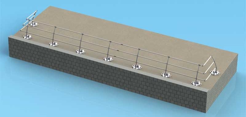
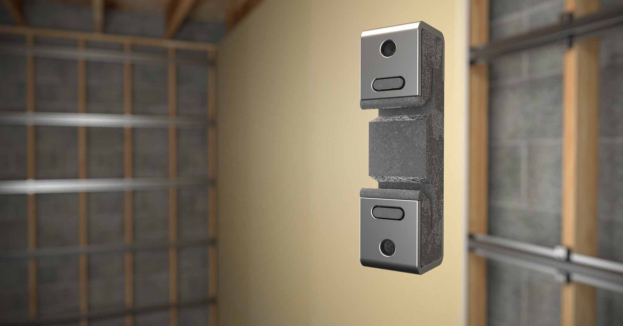
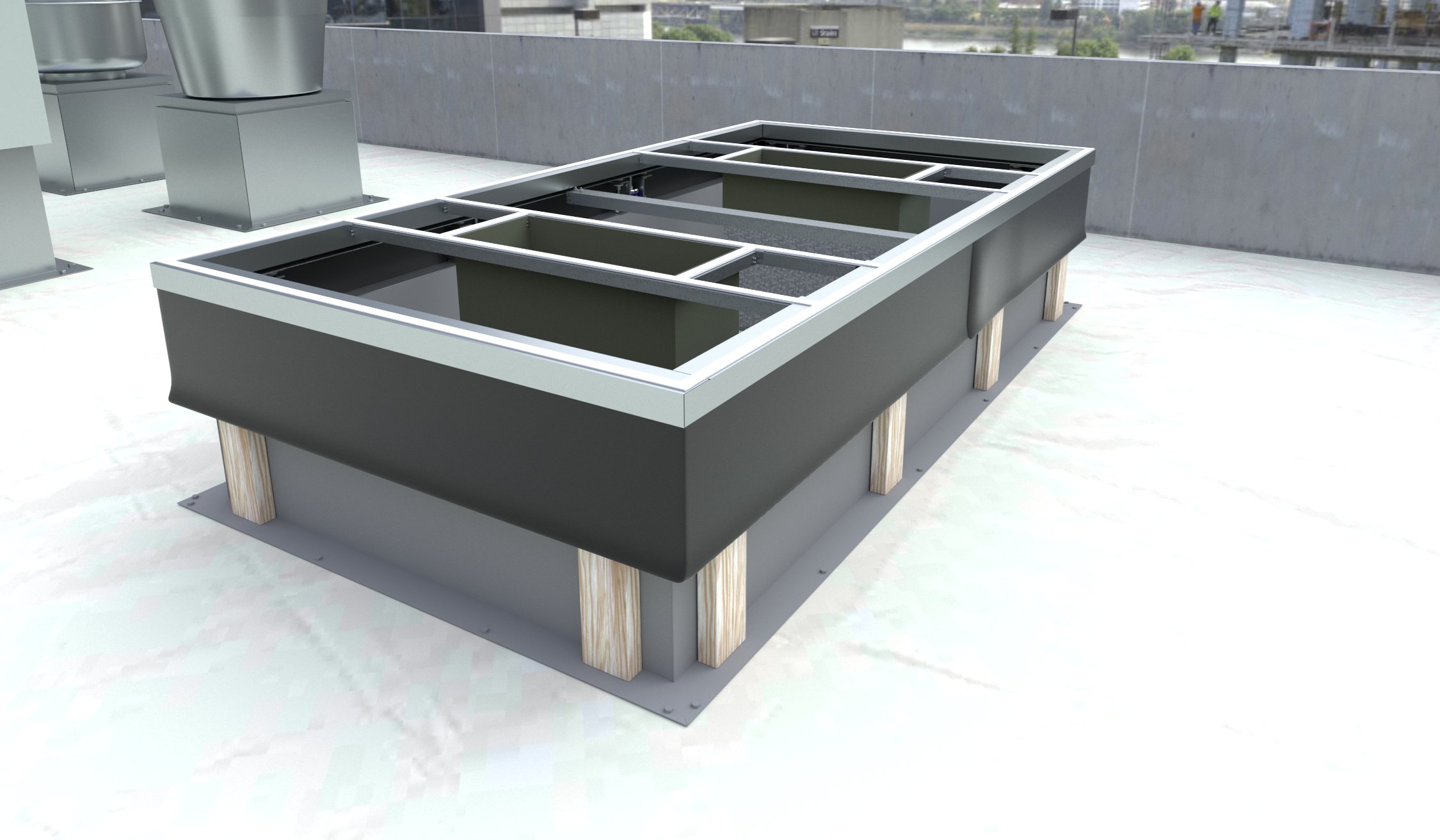
Non-penetrating guardrails are a strong contender among the many possible solutions to fall-related fatalities. When using this method, type should be chosen according to the project and the specific circumstances, and the system’s capabilities and limitations should be carefully weighed.
| SPECIFICATION GUIDELINES |
| The following list shows factors to be included in non-penetrating guardrail system specifications, with examples in parentheses to give readers a clearer idea of how such specifications can be written.
1. Reference standards. 2. Structural load. 3. Rail height. 4. Rail material and construction. 5. Support base material and construction. 6. Receiver post. 7. Hardware. 8. Finishes. 9. Surface protection pads. In most cases, guardrails comprise only a short descriptive paragraph of specifications. It is hoped emphasizing the importance of choosing the right guardrail and demonstrating what a full specifications guide for guardrails can look like will facilitate creation of a separate section for guardrails, to be used in future specifications. Where to write specifications Non-penetrating guardrails are made of metal or PVC, so it might seem the most logical course of action is to place them under Division 05. On the other hand, they are temporary implements on roofs, so placing them under Division 11 or Division 07 (specifically, 07 72 00) is a sound idea, too. The railings referred to in this article can be used either as temporary railings (i.e. for occasional use while working on a roof, or for protecting openings) or—more commonly—permanently placed railings for industry applications. Railings used during construction could meet the requirements of Division 01 at the discretion of the contractor. Ultimately, where the specifications should be written depends on how the architect feels the product has been used on the project. This is why it is important to ensure adequate communication between the parties involved—this way, misunderstandings and, more importantly, safety hazards to workers can be avoided or minimized. |
Andrew J. Miller is the founder and president of Dakota Safety, which specializes in passive fall protection systems and safety products. He is an active member of the Minneapolis St. Paul Chapter of CSI and has more than 30 years of experience in construction product representation, sales, and marketing. Miller can be reached via e-mail at andrew.miller@dakotasafety.com.
Sign up for our weekly newsletter
Architectural materials and methods delivered right to your inbox
- CSI News and Notes: CSI Foundation’s construction camp; CSI spring exam; and more
- CSI News and Notes: CSI’s credentials; CSI conference theme; and more
- To be specific – CSI supports young AECO professionals
- CSI News and Notes: CSI’s foundation scholarships, national conference, and Crosswalk
- CSI News and Notes: AI’s impact; CSI 2024 conference, and more


Read the Latest Issue