Blindside waterproofing and at-grade transitions
Waterproofing is a critical component of the building envelope, a comprehensive system protecting structures from environmental elements. Site-specific conditions, including subsurface drainage, groundwater levels, and building use, dictate the type and extent of waterproofing required. Sheet membranes, bentonite-based systems, and multi-layered composite systems each offer appropriate and effective solutions for different project conditions and performance requirements.
Selecting the appropriate waterproofing system for any given site presents inherent challenges, but these complexities intensify with zero lot line construction, where structures extend directly to property boundaries. In these constrained environments, both installation methodology and product selection become critical success factors, particularly at foundation levels and at-grade locations where proper terminations and transitions determine long-term system performance.
This article examines the unique challenges of blindside waterproofing in zero lot line construction, explores solutions for different shoring systems, and emphasizes the critical importance of proper transition design and execution—areas where most waterproofing failures originate.
Understanding zero lot line construction and blindside waterproofing
In dense metropolitan areas such as New York City, Seattle, Los Angeles, and Washington, D.C., zero lot line construction is often necessary to maximize available space. These projects bring buildings directly to the property line, sometimes on multiple sides. While building codes for zero lot line construction differ by municipality, one constant remains: installing a waterproofing system properly in these conditions is inherently challenging.
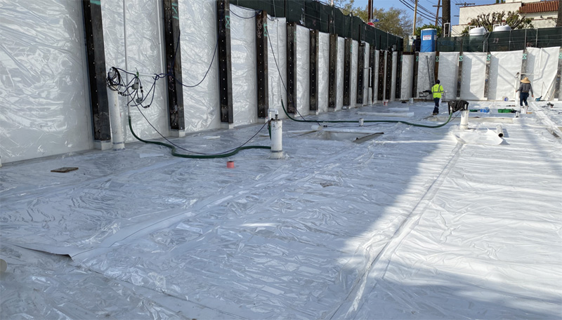
Zero lot line projects require blindside waterproofing, a technique in which the waterproofing system is installed before foundation wall concrete placement. Blindside waterproofing systems can be difficult to design and install, primarily due to their placement sequence and the fact that the drainage and waterproofing systems are installed against the site support of excavation (SOE) or against a neighboring building’s below-grade structure.
Blindside waterproofing is also common in infrastructure applications such as cut and cover tunnel design or any construction site where it is necessary to minimize excavation or what is dictated by site constraints. Blindside waterproofing also allows the building owner to maximize the building footprint by reducing setbacks.
Varying SOE types, including soldier pile lagging, sheet piling, or shotcrete soil nail walls, can create challenging substrate conditions for waterproofing systems. Combined with many varying SOE conditions and the necessity to transition or terminate at grade, there are numerous critical design and installation considerations surrounding zero lot line construction.
Hidden waterproofing
Successful blindside waterproofing presents more challenges than the more straightforward, post-applied application of waterproofing directly to the positive side of an existing concrete foundation wall. With blindside scenarios, structural concrete is applied to the waterproofing membrane, meaning damage or improper installation becomes hidden and inaccessible once concrete is placed.
The SOE type used in blindside construction significantly affects waterproofing detailing and at-grade termination methods. Each approach presents different substrate conditions for the membrane and varying obstacles for waterproofing system continuity.
The two most common shoring construction approaches are soldier pile lagging (wood lagging with steel H-piles) and shotcrete shoring.
Soldier pile and wood lagging
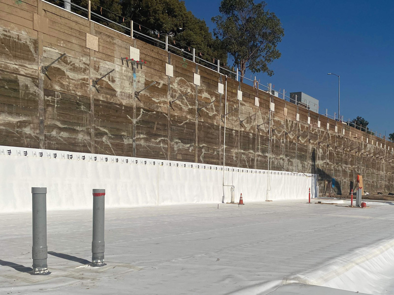
For soldier pile and wood lagging shoring construction, wood lagging boards are installed between steel pile flanges, resulting in a relatively planar surface. Different waterproofing systems have a range of requirements, but most require substrates to be relatively smooth, continuous, and free from voids and protrusions. The substrate should be prepared to prevent potential membrane punctures or ruptures, especially in shotcrete applications where concrete is literally shot directly against the in-place waterproofing membrane. Here, a drainage composite is often used to help create a smooth, uniform surface for the waterproofing system’s application, regardless of water table conditions. Extruded polystyrene insulation (XPS) foam board insulation and plywood are also commonly used.
It is best to provide specific language within the specification that addresses substrate requirements for these conditions. The following language is excerpted from a blindside waterproofing manufacturer’s guide specification:
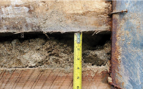
Blindside substrate preparation: Wood lagging shoring should extend to the lowest level of the waterproofing installation with any voids or cavities exterior of the lagging timbers filled with compacted soil or cementitious grout. The interior surface of lagging boards should be planar, with no greater than 25.4 mm (1 in.) variance in a 300-mm (12-in.) plane, and fit tightly together with gaps less than 25.4 mm (1 in.). Gaps greater than 25.4 mm (1 in.) should be completely filled with cementitious grout, compacted soil, wood, XPS (138 kPa [20 psi] min.), or manufacturer approved polyurethane sprayfoam. Ensuring the void is filled, plywood or other surface treatment may be used over large lagging gaps up to 150-mm (6-in.). XPS protection board (138 kPa [20 psi] min.) or manufacturer approved drainage composite may be installed over gaps up to 50 mm (2 in.). Gaps greater than 50 mm (2 in.) should be completely filled with cementitious grout, compacted soil, wood, XPS (138 kPa [20 psi] min.), or manufacturer approved polyurethane sprayfoam. All lagging board nails and other mechanical projections shall be removed or flattened. Install a protection material over all soldier piles with raised lagging hanger bolts, form tie rods, or other irregular surfaces; protection material should extend a minimum of 150 mm (6 in.) to both sides of the steel piling. A base drain system should be connected to an operative water discharge system.1
Back-lagged configuration challenges
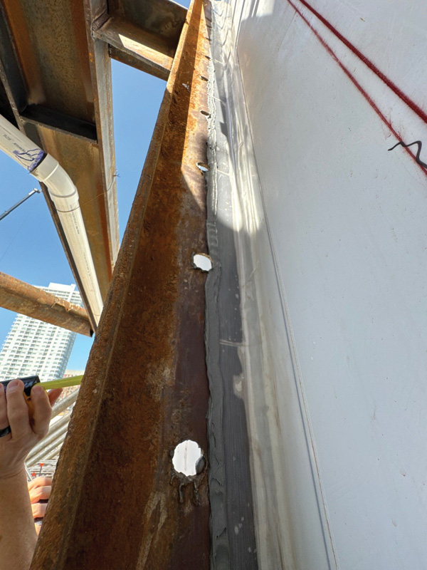
The most common soldier pile lagging configuration is a “front-lagged” condition. However, to maximize property footprint or to accommodate for mis-driven piles or buried obstructions, lagging is sometimes installed on the back flange of piles, closest to the soil, creating a “back-lagged” configuration.2 Here, the steel pile flanges protrude, interrupting the plane of the blindside membrane. In back-lagged conditions, designers have two options:
(a) Contour the waterproofing system around each soldier pile by infilling gaps around flanges with manufacturer-approved filler such as tapered XPS foam material; or
(b) Terminate the membrane at each pile flange and restart on the opposite side of the pile
Option (a) maintains continuous barrier protection across the pile but requires close coordination with the structural design team to ensure added filler does not conflict with rebar placement. This option is often impractical due to structural conflicts.
Option (b) essentially treats each bay between piles as its own waterproofed panel. This approach relies more heavily on careful detailing since it creates membrane terminations at every pile. The membrane must be carefully sealed and terminated to each steel beam face with tape, sealant, mastic, or some combination thereof, which can then introduce additional risks dependent on installation quality and proper adhesion of the waterproofing system to the steel flange. Enhanced waterproofing detailing and onsite inspection of the in-place waterproofing system are recommended to ensure proper installation when this SOE configuration is used.
Shotcrete shoring systems
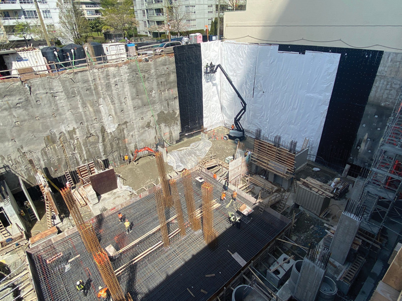
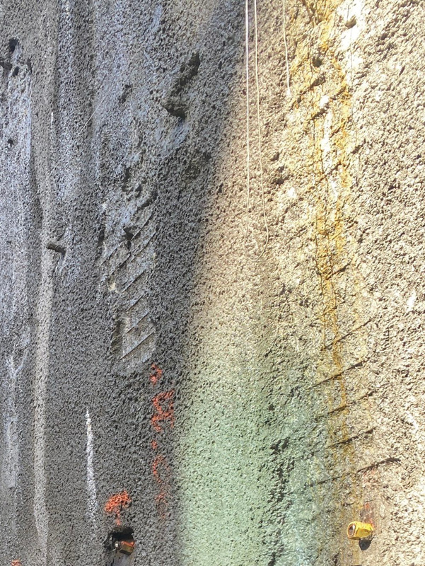
More commonly used on Canadian projects, shotcrete shoring involves spraying concrete directly onto native excavated soil with reinforcement mesh to create a continuous concrete retaining wall. Soil nails are often used in conjunction to reinforce the retaining wall. The advantage of shotcrete shoring lies in installation speed. However, shotcrete surfaces can be uneven or non-planar, and rebound aggregate can create voids or rough areas. It is often necessary to scrape or broom the shotcrete surface to remove high spots or apply a skim coat to fill depressions, thereby achieving a suitable substrate for membrane installation. Further, membranes must conform to the shotcrete shoring substrate to prevent voids that could potentially compromise the system when the structural foundation wall concrete is placed.
Adjacent structure complications
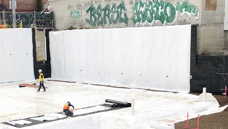
Blindside waterproofing in zero lot line conditions, constructed directly against adjacent structures, can present multiple challenges. Special care is required during the waterproofing system application. It is typically not acceptable to use an adjacent structure’s foundation wall as a substrate for the blindside waterproofing system. Rigid XPS foam board, rockwool insulation, or other suitable filler materials can provide appropriate substrate conditions. The blindside waterproofing system then uses this buffer material as the application substrate. The substrate must be structurally sound to support the installed waterproofing system’s weight. In these instances, the use of mechanical fasteners on adjacent structures may be limited or prohibited entirely.
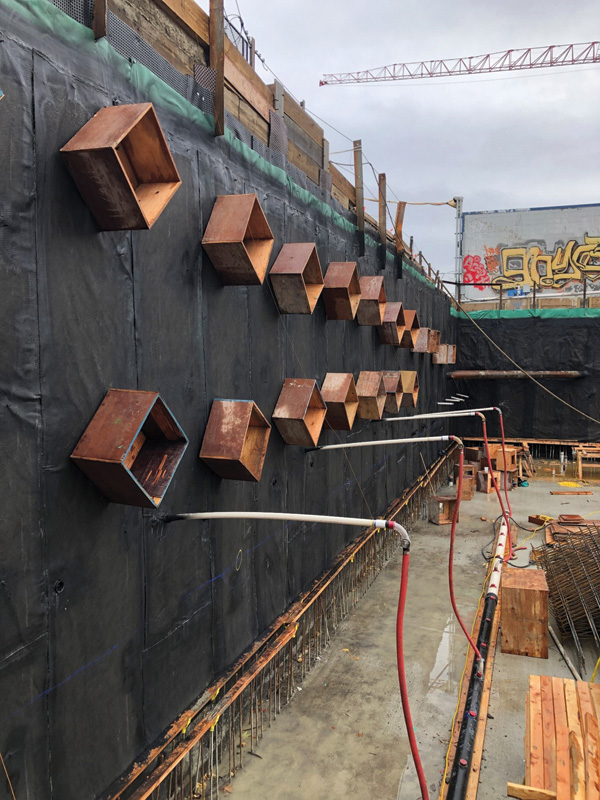
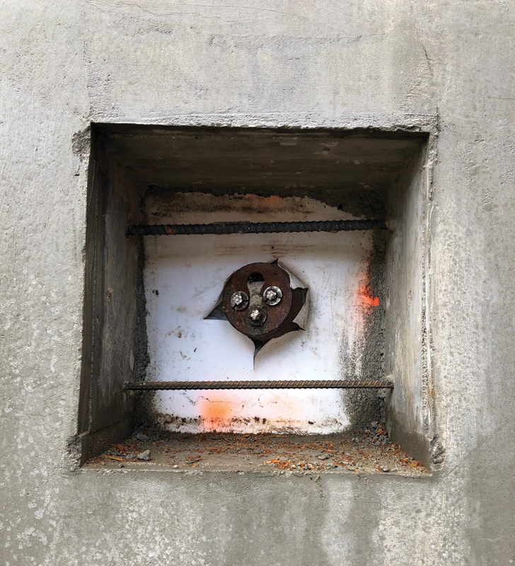
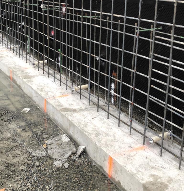
Detensioning and tie-back system
Post concrete wall placement, tie-back, or soil nail detensioning requires blockouts to be constructed around the anchor heads. These blockouts create access “windows” for post-tensioning operations. After waterproofing detailing is done, they are filled with concrete to complete the structural wall. Typically, blockouts are limited in size to avoid interfering with reinforcement placement, which complicates waterproofing patch application. It is imperative to protect the installed blindside waterproofing membrane within any blockouts from overspray or concrete contamination.
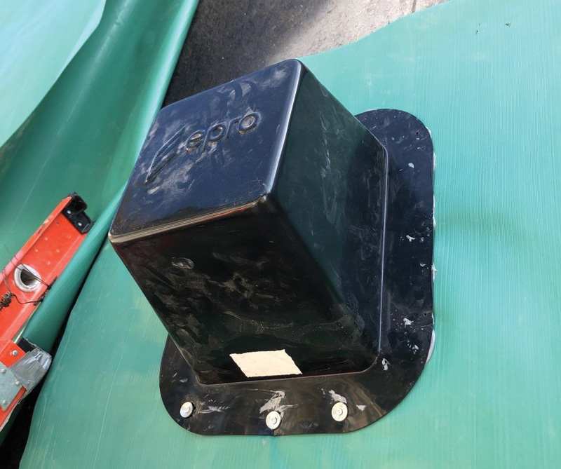
Tie-back waterproofing detailing requires installing a suitable cover that cleanly transitions and integrates with the in-place blindside waterproofing membrane. Some waterproofing manufacturers provide pre-fabricated tie-back covers for this purpose, potentially eliminating the need for field-fabricated sheet metal or plywood covers. Due to the complexity and inherent challenges of tie-back detailing, some manufacturers require injection tube waterstop installation as secondary protection.
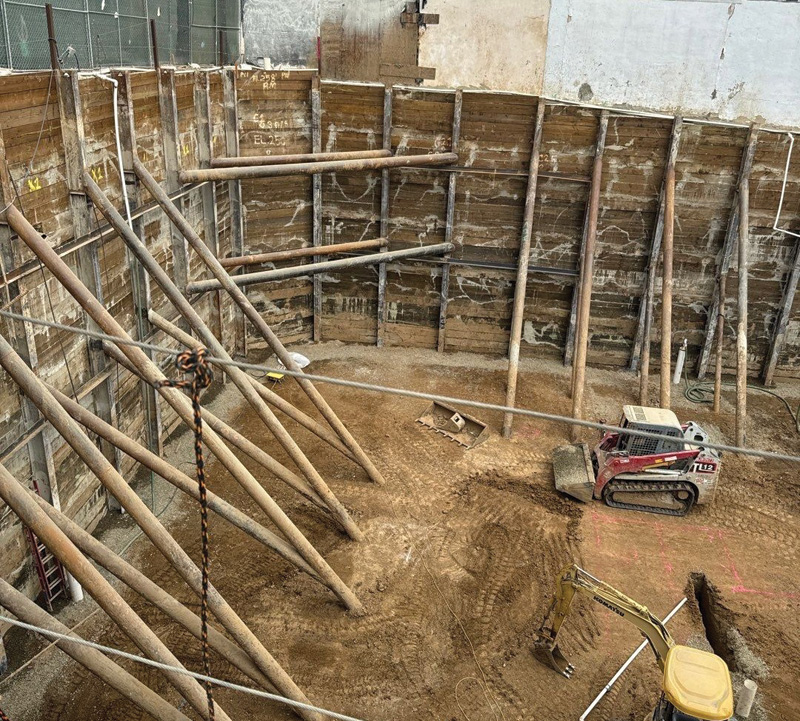
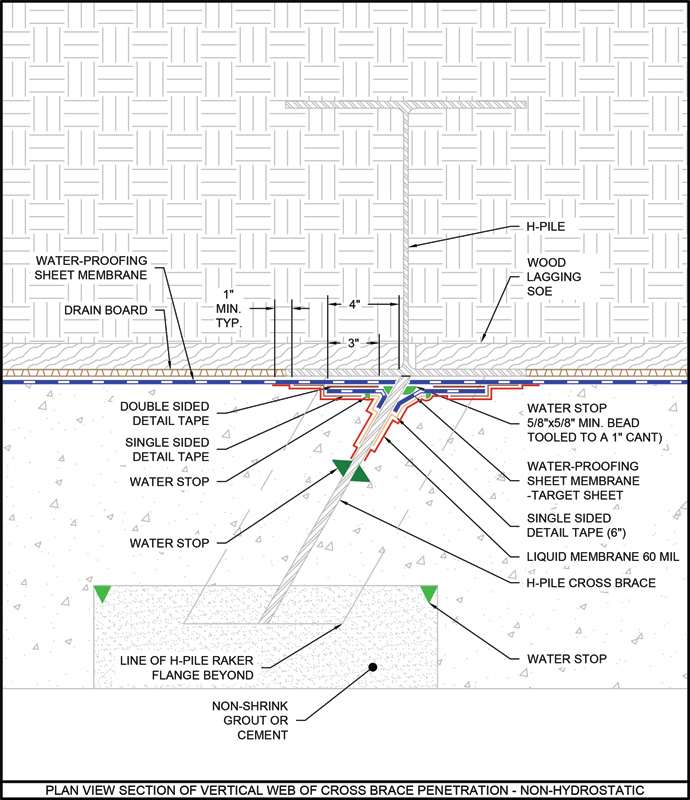
SOE bracing challenges
Horizontal struts spanning across excavations, walers distributing loads along the shoring wall, and inclined rakers transferring loads to foundation elements all create additional detailing requirements and potential water ingress points.
Struts, which resist lateral earth pressures through compression across the excavation width, must be carefully detailed where they penetrate or interface with the waterproofing membrane. Walers, running parallel to the excavation wall to distribute tie-back or soil nail loads, create linear obstructions that require continuous membrane transitions. Rakers, extending at angles from the shoring wall to stable foundation elements, present complex geometric challenges for membrane detailing where it interfaces with the shoring.
Some bracing elements may be removed during various construction phases. Struts are typically removed during concrete placement, while rakers are often removed after concrete placement. This phased removal sequence introduces the potential for damage to installed waterproofing and requires waterproofing details that accommodate both the presence of these elements and their subsequent removal without compromising membrane integrity. As a result, careful detailing and coordination are required at these structurally complex locations.
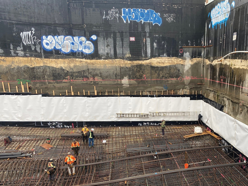
Rebar placement and concrete forming
Ideally, the number of penetrations through blindside waterproofing systems should be limited, especially in below-water-table conditions. Reducing the number of nelson studs, dowels, rebar support elements, and form ties decreases complexity and labor-intensive detailing where proper execution is critical.
In all instances, penetrations must be securely positioned and immobile during concrete placement, particularly for shotcrete wall applications, to prevent damage to the installed blindside waterproofing system. Rebar supports should not create point load on the installed blindside waterproofing system; when necessary, concrete spacers or dobies with flat surfaces should be used against the membrane.
Following concrete reinforcement installation, close inspection of the installed waterproofing membrane should be performed to ensure no punctures, tears, or damage. Any damage should be noted and repaired according to manufacturer guidelines prior to concrete placement.
Drainage system integration
When sites require a drainage composite, it is applied first to the SOE substrate, with the blindside waterproofing membrane applied over the drainage composite. A subslab drainage system must be designed to accommodate water collection once installed. Drain outlets must be connected to the drainage composite and cast through the base of the foundation wall or through the footing to the interior subgrade where sumps or other water management systems discharge collected water from the wall drainage composite. Traditional base-of-footing drain tile systems cannot be implemented since the footing aligns with the SOE.
Concrete placement challenges
Shotcrete foundation wall applications are increasingly prevalent in the United States and Canada as an alternative to traditional cast-in-place concrete foundation walls. Shotcrete eliminates the need for form board erection and can typically be accomplished quickly and efficiently. However, this concrete placement method creates unique challenges for blindside waterproofing systems, particularly considering that aggregate impacts the installed membrane at velocities exceeding 27 m per second (60 mph).3
In cases like this, waterproofing membrane seam performance becomes essential, as does adequate puncture resistance ratings that can accommodate shotcrete application forces. Proper substrate preparation is critical to prevent voids behind the membrane, which can lead to system rupture during concrete placement, and to eliminate sharp protrusions that can cause punctures during concrete placement.
Shotcrete placement techniques must prevent shadowing behind reinforcement since blindside waterproofing membranes are designed to function with structural concrete fully consolidated against the installed membrane. Voids in shotcrete from improper placement can cause the installed system to rupture under positive-side hydrostatic pressure. Further, if waterproofing system breaches occur, areas with poor shotcrete adhesion allow water migration within the wall assembly, which may ultimately reach cracks, joints, or penetrations and result in water ingress.
Concrete overspray presents a significant challenge during shotcrete installations, particularly at lift terminations. To prevent contamination of adjacent waterproofing, contractors must implement adequate protection measures and ensure proper installation methods. When overspray does occur, it can compromise the bond of the waterproofing membrane. If contamination occurs, consult the membrane manufacturer for proper repair procedures, which typically involve cleaning (if possible) or patching the affected areas.
Numerous waterproofing failures have resulted from improper shotcrete application practices. To address this issue, projects should establish minimum qualifications for shotcrete nozzlemen and implement enhanced quality control/quality assurance procedures. Many waterproofing manufacturers now require shotcrete applicators to hold ACI or ASA certification and demonstrate at least 500 hours of shotcrete experience before offering performance warranties.
The critical importance of at-grade transitions
Waterproofing system performance depends critically on two factors: appropriate detail design and proper installation that follows these details at transitions and terminations. Analysis of waterproofing failures indicates that many occur at system edges where installations begin, terminate, or transition between different materials or substrates. These areas present nuanced design challenges and may require specialized details depending on the connecting systems at grade or special conditions such as back-lagged shoring or shotcrete shoring SOE. Transition strategies for blindside waterproofing must also be adapted to different shoring methods. This section outlines concerns at these critical areas and presents solutions and best practices.
Wood lagging transitions
For sites where the top of the lagging is accessible, most pre-applied vertical foundation wall waterproofing membranes terminate below the at-grade slab construction joint. The uppermost lagging boards are removed, and piles are cut off to expose the top edge of the pre-applied membrane and the positive side of the concrete foundation wall.
Protecting the membrane from burns and damage caused by soldier pile and wood lagging removal is critical. Cement board backing typically provides effective protection. If the pre-applied below-grade membrane is damaged, the damaged area must be repaired prior to detailing the at-grade transition. The key to success for at-grade transitions is achieving a well-adhered, continuous positive lap over the in-place blindside foundation wall waterproofing system. For this to be accomplished successfully, a clean, fully adhered, non-damaged membrane must be available to perform an adequately detailed transition.
Limited access conditions
For project sites where access is limited and soldier pile lagging cannot be removed, extending a “tail” or transition strip of the below-grade shoring waterproofing membrane above the construction joint and at the top of wall maintains system continuity in shoring wall to suspended slab applications.
Two approaches are available:
- Folded transition—Fold this transition strip over and sandwich the extended membrane tail into the deck waterproofing to provide a seamless transition.
- Vertical termination—Terminate on the vertical shoring and transition the horizontal deck waterproofing up the vertical face.
Care must be taken to ensure the membrane “tail” remains undamaged and clean for a successful transition to the above-grade waterproofing system. It will be exposed until the grade-level slab is poured and the above-grade waterproofing system is applied. Inspection and quality control are critical, requiring commitment from the general contractor and follow-on trades.
Material compatibility considerations
Depending on project design, above-grade waterproofing systems, such as hot-applied rubberized asphalt, may transition to below-grade blindside waterproofing systems. In this case, confirming material compatibility between different membrane systems is essential. Hot rubberized asphalt, commonly used as a deck waterproofing membrane, can damage below-grade waterproofing systems at transitions due to high installation temperatures. A transition membrane, such as a modified-bitumen self-adhesive sheet, may need to be applied to the blindside waterproofing to accomplish an effective tie-in.
Detailing sealants, fluids, or adhesive backing for tie-ins with above-grade air barrier systems may not have effective adhesion or be compatible long term with the below-grade waterproofing system. Consulting with the air barrier manufacturer and written documentation to determine compatibility is recommended.
Shotcrete shoring transitions
Shotcrete shoring often causes more complications than soldier pile shoring. Due to space constraints, repairing below-grade waterproofing membrane damage from the concrete shoring removal process can be exceptionally challenging for zero-lot-line projects. Coordinating the concrete removal and membrane repair process early in pre-construction meetings is essential.
Similar to soldier pile shoring construction, here, the vertical foundation wall waterproofing membrane is installed up to grade elevation. Cement board or plywood is placed between the vertical foundation wall waterproofing system and shotcrete shoring to protect the membrane during the concrete removal process. This provides membrane protection at grade level and ensures a planar substrate for membrane application, enhancing membrane adhesion to the foundation wall at such a high-risk area. Once the shotcrete shoring and protection board are removed, above-grade wall or deck waterproofing can transition into the below-grade waterproofing system.
Best practices and project management
It is not uncommon for one manufacturer’s product to be used for below-grade shoring waterproofing and another manufacturer’s system for above-grade waterproofing. Ensuring compatibility and proper transitioning is the responsibility of the designer, in consultation with system manufacturers. To help resolve this challenge, many waterproofing manufacturers provide systems for both below-grade shoring and above-grade waterproofing. Specifying manufacturers that have clear and concise details for these critical transitions is recommended.
Blindside waterproofing presents notable challenges, but careful planning and early collaboration between stakeholders ensures successful outcomes. Waterproofing consultants, product manufacturers, and applicators can offer valuable expertise regarding complex tie-in details, system compatibility, and strategic sequencing, and can identify conflicts early in the design process. The complete set of SOE plans should be provided to the applicator prior to construction so suitable, site-specific shop drawings can be developed for the project. Engaging directly with waterproofing membrane manufacturers to review specific project conditions often yields valuable recommendations for project-specific details and proper application procedures. Preconstruction meetings that address waterproofing inspection requirements, including substrate requirements, installed waterproofing exposure limitations, and repair procedures, are an essential component of the construction process.
The unfortunate price of failed blindside waterproofing
Conventional waterproofing failures typically manifest as basement seepage that can be addressed through exterior excavation and repair. However, foundation wall excavation is not feasible for projects that use blindside waterproofing. Failures often require extensive remedial measures such as costly chemical injection from inside the structure. Potential expenses include structural damage, business interruption, legal liability, and reputation damage. Therefore, careful design, proper application, and enhanced quality control measures are essential. Attempting to remediate a failed blindside waterproofing system can cost anywhere from 10 to 20 times the original installation while never achieving the long-term reliability of a properly executed initial system. Ultimately, it can prove a costly mistake to turn a blind eye to blindside waterproofing.
Notes
1 Refer.
2 See “Mastering blindside waterproofing: A proactive, integrated approach”.
3 Read “Material Velocity at the Nozzle” Shotcrete (Fall 2013), page 22.
Author
As director of product development for EPRO, Scott Schendel manages an innovative portfolio of products that help protect structures in any site conditions, at any location. He has more than 15 years of relevant building envelope experience with specific expertise in below-grade waterproofing for new construction and restoration applications. From large-scale civil infrastructure to elevator pits and planters, Schendel has a wide range of project experience. He is a member of the SWR Institute and regularly collaborates on waterproofing projects across North America.
Key Takeaways
Blindside waterproofing in zero lot line construction demands careful system selection, precise detailing, and expert installation. Success hinges on managing substrate variability, transition complexity, and coordination among trades. Poor execution can lead to costly, irreversible failures, making early planning, material compatibility, and rigorous quality control essential to long-term waterproofing performance.
Sign up for our weekly newsletter
Architectural materials and methods delivered right to your inbox
- CSI News & Notes: CSI’s impact earns official recognition; celebrate leaders, mentors, and innovators; and more
- CSI News and Notes: CSI spring certification exams open; scholarships available; and more
- CSI News & Notes: CSI MSR heading to San Diego; spring certification exams open; and more
- To Be Specific: Why CDT Should Be Your First Move
- CSI News & Notes: CSI Fellows share member benefits; and a New Year’s Resolution to keep
Related Products

Read the Latest Issue