The envelope challenge: Meeting Massachusetts’ Stretch Code
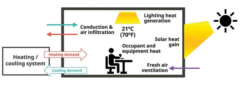
Massachusetts’ Stretch Code is arguably the most stringent building energy code in the United States. It was developed in response to Massachusetts’ 2021 Next Generation Road Map Act. According to Paul Ormond, from the Massachusetts Department of Energy Resources, the code is designed to “crush heating” loads, facilitating building decarbonization through heat-pump deployment. While heating loads are typically not the largest energy load in Massachusetts’ buildings, even at an estimated 15 percent of the total energy use intensity (EUI), these loads limit the practical implementation of electric heat pumps (Figure 1).
Based on the 2021 International Energy Conservation Code (IECC), Massachusetts has incorporated additional challenging thermal performance requirements for above-grade vertical building envelopes. These requirements represent a step change from any other jurisdiction in the U.S. and have caused compliance challenges across the entire design-build-material value chain. It has become especially challenging to design and effectively specify vertical above-grade building envelopes to ensure the building is stretch code-compliant. This article illustrates how to manage those challenges.
Note that the Massachusetts Stretch Code uses inch-pound units for all its requirements. When reviewed herein, these are converted to SI units, with the code’s inch-pound units following.
Envelope-first focus
At its core, the Massachusetts Stretch Code is designed to preserve building envelope performance. It is the first energy code in the U.S. to fully address the impact of thermal bridging on vertical building envelope U-factor. It also has stringent air infiltration requirements based on the 2024 IECC and 75 percent ventilation heat recovery.
Critically, it does not permit designers to trade off reductions in vertical envelope thermal performance with increasing roof performance. This often-used strategy would lead to increases in the insulation of the already high-performance roof and degradation of the vertical envelope. Roofs, below-grade walls, floors, slab-on-grade floors, and opaque doors with minor exceptions must comply with the values in Table C402.1.4 of the base 2021-IECC code. The performance of the vertical envelope also cannot be traded off for increases in performance of systems such as HVAC and lighting. These systems typically have much shorter service lives than the envelope and are more easily upgraded to the newest technology on a shorter lifecycle than the building envelope. In contrast, the performance choices made for the building envelope are baked in for many decades. There is a maximum vertical envelope thermal transmittance (U-factor) limit (also known as a backstop) in all compliance paths.
Additional thermal performance requirements apply when glazed walls—curtain walls, storefronts, or window walls accompanied by spandrel—are used. The requirements were designed to make it difficult, but not impossible, to design with glazed walls, which have higher transmittance than other wall types.
For designs where glazed walls (vision plus spandrel area) cover less than or equal to 50 percent of the wall area, the area-weighted U-factor must not exceed 0.73 W/m2K (0.1285 BTU/hr∙sf∙F). Where glazed walls comprise more than 50 percent of the wall area, the U-factor maximum is raised to 0.91 W/m2K (0.16 BTU/hr∙sf∙F). Note that “glazed wall area” should not be confused with “window-to-wall” ratio. The latter is the transparent area divided by the total wall area.
To prevent the tradeoff of the often-overestimated spandrel performance with transparent performance in glazed walls, the Massachusetts code also mandates a maximum glazed wall vision U-factor of 1.4 W/m2K (0.25 BTU/hr∙sf∙F). [Note: this is not the center-of-glass U-factor.] As described later, this maximum is moot in practice because much higher performance from the vision areas is typically needed.
Multiple compliance paths
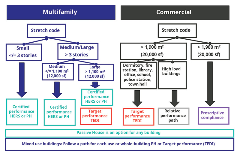
- Prescriptive path: Limited to buildings with a floor area less than 1,860 m2 (20,000 sf), each building component must meet a prescribed performance. There is a component performance alternative within this path that allows for a tradeoff between envelope components, with some limits as described above. This sets the maximum envelope thermal performance (backstop) for the relative and target compliance paths.
- Relative performance path: Limited to use in high-load buildings, such as laboratories and hospitals. Based on Section 407 of the IECC, building simulation must show that the energy performance of the proposed building is better than that of a comparable building based on the code’s prescriptive requirements. However, building envelopes must comply with the prescriptive path’s envelope component alternative and limits.
- Target performance path: Must be used for commercial buildings more than 1,900 m2 (20,000 sf) that are not high-load buildings. It is one of three choices for multifamily buildings over three stories and more than 1,100 m2 (12,000 sf). It requires compliance through building simulation. The simulation must show that it meets an annual building EUI target and a performance target based on the thermal energy transfer across the building envelope called Thermal Energy Demand Intensity (TEDI). Figure 3 illustrates the concept. There is a TEDI requirement to limit both heating and cooling demands, ensuring that overheating is also controlled. An envelope backstop based on the prescriptive requirement also applies.
- Home Energy Rating System (HERS): One of the compliance paths for multifamily buildings of any size with additional prescriptive requirements.
- Passive House Certification: Can be used for any building type and is one of the compliance choices for any multifamily building. Compliance is certified on as-built performance. Additional prescriptive requirements exist for roof reflectance, electrical power, documentation, maintenance, and commissioning.
Thermal bridge mitigation requirements
Fenestration assembly U-factors account for reductions in thermal performance in windows due to thermal effects at the edge of glass and the frame. Only recently have thermal bridges within opaque walls—including curtain wall spandrels and rainscreen panels (known as clear field thermal bridging)—been considered for Massachusetts’ Stretch Code compliance. Thermal bridges at transitions between envelope systems and at penetrations have also been ignored. Estimates in BC Hydro’s Thermal Bridging Guide (TBG), created by Morrison Hershfield (now Stantec), and referenced by the British Columbia Step Code and Massachusetts Stretch Code, suggest thermal bridging degrades the performance of opaque building envelopes by 20 to 70 percent.
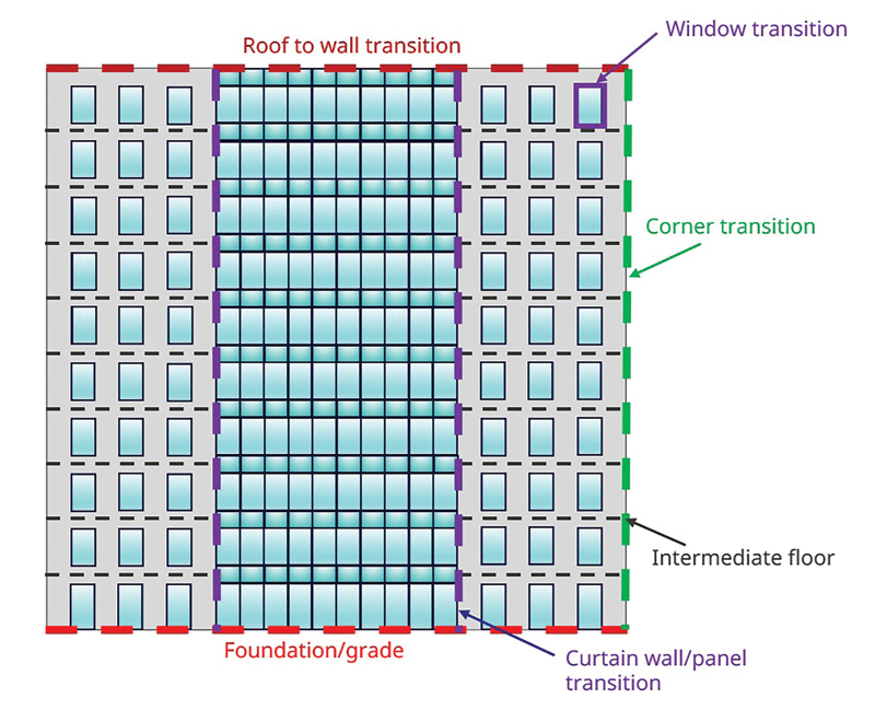
The stretch code requires thermal bridging in 11 different facade assemblies and linear interfaces to be accounted for, including:
- Cavity insulation between wall framing
- Brick ties holding brick panel sections to framing
- Fasteners for attaching wall panels to framing
- Balcony-to-wall interfaces
- Fenestration-to-wall transitions
- Wall-to-roof transitions (parapets)
- Wall-to-grade transitions
- Corner intersections
- Interior floor-to-exterior wall transitions
- Interior wall-to-exterior wall transitions
- Brick shelves
Thermal bridging is accounted for by applying thermal derating values to clear field U-factors, assigning thermal transmission values to linear transitions (psi-factors), and point thermal bridges (chi-factors) in the opaque wall areas of the vertical building envelope. The overall thermal performance of the vertical building envelope is an area-weighted average of the thermal transmittance of the derated opaque elements and the vision glazing.
The Massachusetts Stretch Code provides three alternative approaches to assigning thermal bridge derating values:
- Using prescriptive thermal conductance values that are defined for each type of thermal bridge. These values assume a very high thermal conductance. Adopting this compliance path causes many challenges in meeting the envelope thermal performance requirements.
- Reference thermal conductance values from the TBG when using assemblies listed in this guide. This path provides a way for design teams to more easily mitigate thermal bridging to ease compliance, while minimizing cost and complexity.
- 2D or 3D thermal simulation of the proposed clear field, and linear and/or point thermal bridge mitigation details. A 3D analysis is required for assemblies with lateral heat flow or thermal bridging in multiple planes.
For assemblies not listed in TBG, simulations must be done or the prescriptive values used.
Stretch code impacts on glazed facades
The following examples illustrate the impact of thermal bridge mitigation and area-weighted U-factor requirements in facades containing glazed walls. The first has a mix of curtain wall (<50 percent of the wall area) and punched opening windows. The second is covered entirely by a curtain wall.
Facade example one: Mixed fenestration, low-glazed wall
An example elevation including a center strip of curtain wall (glazed wall system) flanked by punched windows in a steel-framed rainscreen wall is shown in Figure 4. The rainscreen wall and curtain wall spandrel are considered clear fields for thermal derating purposes. Linear thermal bridging at transitions is shown as dashed lines. In this example, the window-to-wall ratio is 45 percent (total transparent area divided by total wall area), and the percentage of glazed wall area (total area covered by a glazed wall, which includes spandrel area, divided by total wall area) is 42 percent. As noted above, the Massachusetts Stretch Code requires the area-weighted U-factor of the vertical wall to not exceed 0.730 W/m2K (0.1285 BTU/hr∙sf∙F) for glazed wall areas up to 50 percent.
Rainscreen wall
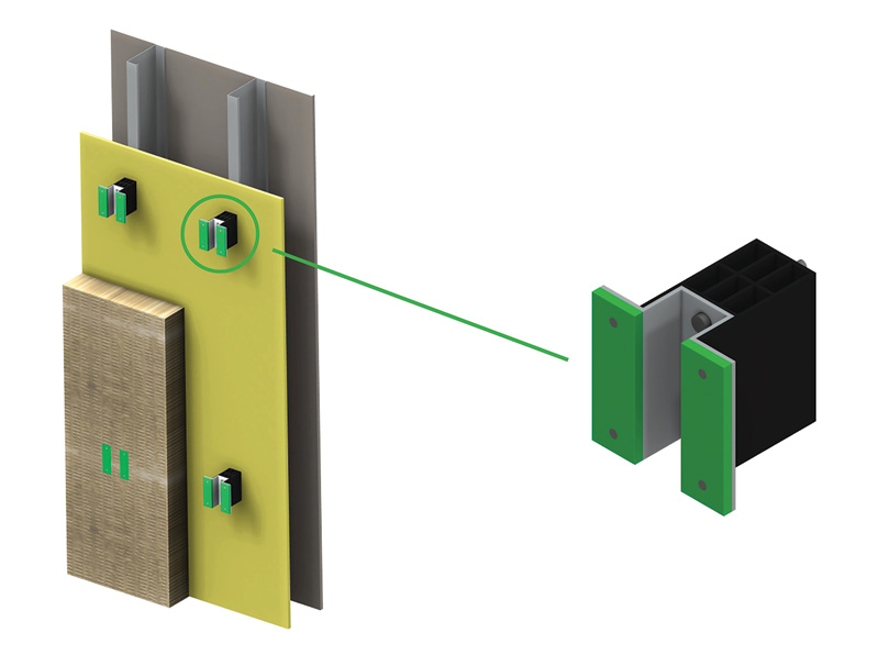
In this example, the rainscreen wall is thermally mitigated by incorporating RSI 2.96 (R16.8) continuous exterior insulation and using thermally broken cladding attachment clips with 610 mm (24 in.) vertical spacing. This assembly’s derated clear field U-value is 0.33 W/m2K (0.058 BTU/hr∙sf∙F) as reported in the TBG V1.6 or higher for Detail 5.1.95. See detail in Figure 5.
Curtain wall spandrel
The example curtain wall spandrel is also thermally efficient, utilizing structurally glazed, high-performance, triple-pane, insulating glass (IG) with two low-e coatings; argon gas fill and warm edge spacer [the center of glass U-factor is 0.67 W/m2K (0.118 BTU/hr∙sf∙F)]; and 130 mm (5 in.) of insulation. A resultant clear field U-factor, derated for thermal bridging, of 0.65 W/m2K (0.114 BTU/hr∙sf∙F) for a 1.5 x 1.2 m (5 x 4 ft) spandrel panel is reported by the TBG V1.6 or higher for Detail 4.1.3 for this system. See Figure 6.
Curtain wall transparent glazing
In this example, the curtain wall’s transparent glazing similarly includes structurally glazed, high-performance, triple-pane IG with two low-e coatings, argon gas fill, and warm-edge spacer [center of glass U-factor of 0.67 W/m2K (0.118 BTU/hr∙sf∙F)]. This provides a vision fenestration assembly U-factor of 0.94 W/m2K (0.165 BTU/hr∙sf∙F). See Figure 6.
Punched opening windows
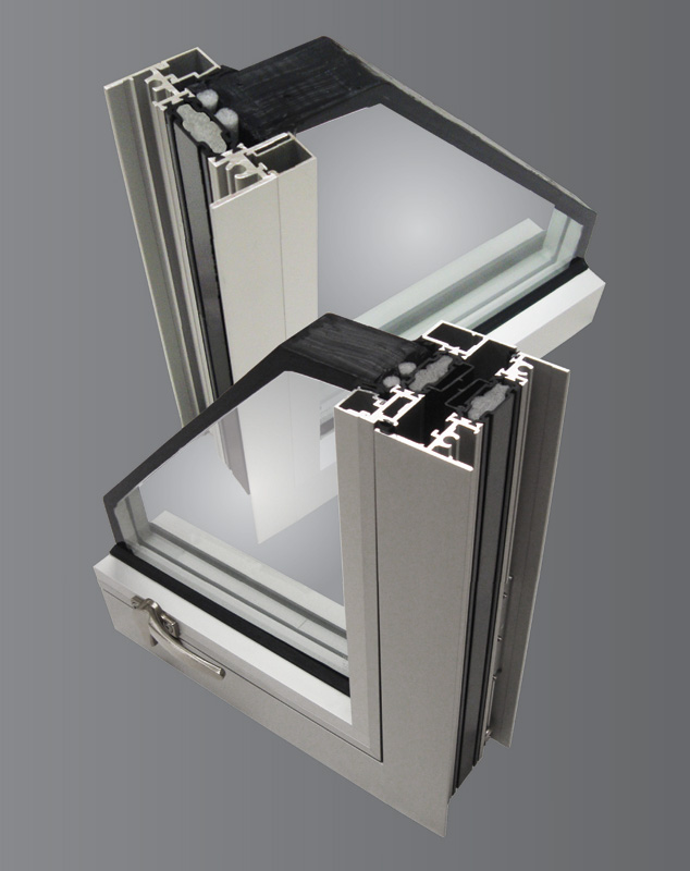
The high-performance, triple-glazed, fixed windows in this example deliver a fenestration U-value of 0.91 W/m2K (0.16 BTU/hr∙sf∙F). To achieve this performance, this commercial window example (Figure 7) uses wide 44-mm (1.7 in.) polyamide (PA) thermal barriers to reduce conduction, with foam to reduce convection.
Area-weighted U-factor calculation: Example facade one
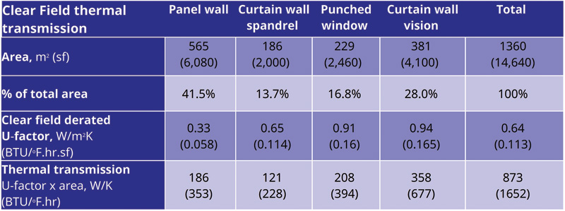
Figure 8 summarizes the area-weighted U-factor and total thermal transmission of the clear field areas—opaque rainscreen and spandrel panels derated to account for thermal bridging—and the total transparent fenestration U-factor.
The area-weighted clear field U-factor of 0.64 W/m2K (0.113 BTU/hr∙sf∙F) must be derated yet further to account for thermal bridging at the linear interfaces. Thermal bridging will add to the clear field thermal transmission of 873 W/K (1,652 BTU/hr∙F).
Figure 9 summarizes the increase in thermal transmittance of the wall due to all identified linear thermal bridges in the example facade, when using:
- The Massachusetts Stretch Code’s conservative prescriptive linear derating values (prescriptive linear derating).
- The reference derating method, using details from the TBG that better mitigate thermal bridging than the prescriptive assumptions (reference linear derating).
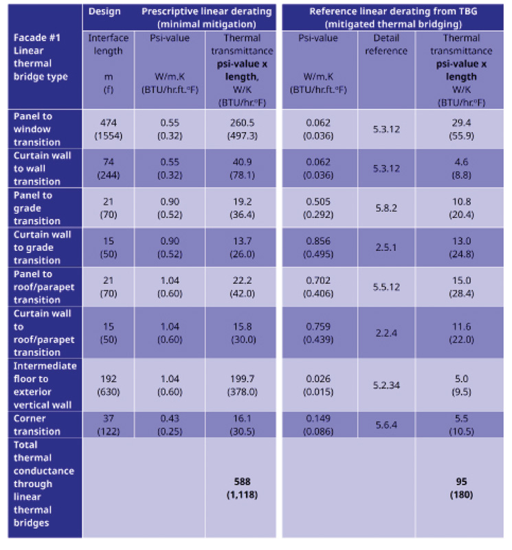
Figure 9 demonstrates the benefit of designing with TBG-referenced transition details, which reduce thermal transmission from 588 to 95 W/K (from 1,118 to 180 BTU/hr∙F). In this example, the prescriptive thermal bridging transmittance is 68 percent of the clear field transmittance. Even with mitigated thermal bridging, the thermal transmittance at the interfaces is more than 10 percent of the clear field transmission.
Due to the many small punched opening windows, thermal bridging at the window-to-wall transitions dominates the linear transmittance, indicating that (i) special attention should be paid to those areas to mitigate the heat loss and (ii) designs which minimize those transitions—such as using long strip windows to wrap the building, large windows, or expanses of curtain wall rather than small punched opening windows—can minimize such losses.
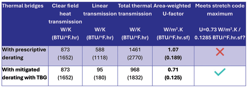
Further, it is clear from the area-weighted U-factor calculations summarized in the table in Figure 10 that it is not possible to meet the Massachusetts Stretch Code area-weighted U-factor requirement without mitigating thermal bridging. Even then, it is only possible to meet the requirements by using very high-performance, triple-pane windows and curtain wall with assembly U-factors of 0.94 W/m2K (0.165 BTU/hr∙sf∙F) or less, not including spandrel. This performance is significantly higher than the prescriptive U-factors of 1.7 and 1.8 W/m2K (0.30 and 0.32 BTU/hr∙sf∙F) for fixed and operable fenestration, respectively. It is also much more stringent than the minimum vision curtain wall U-factor of 1.4 W/m2K (0.25 BTU/hr∙sf∙F).
Facade example two: Highly glazed wall
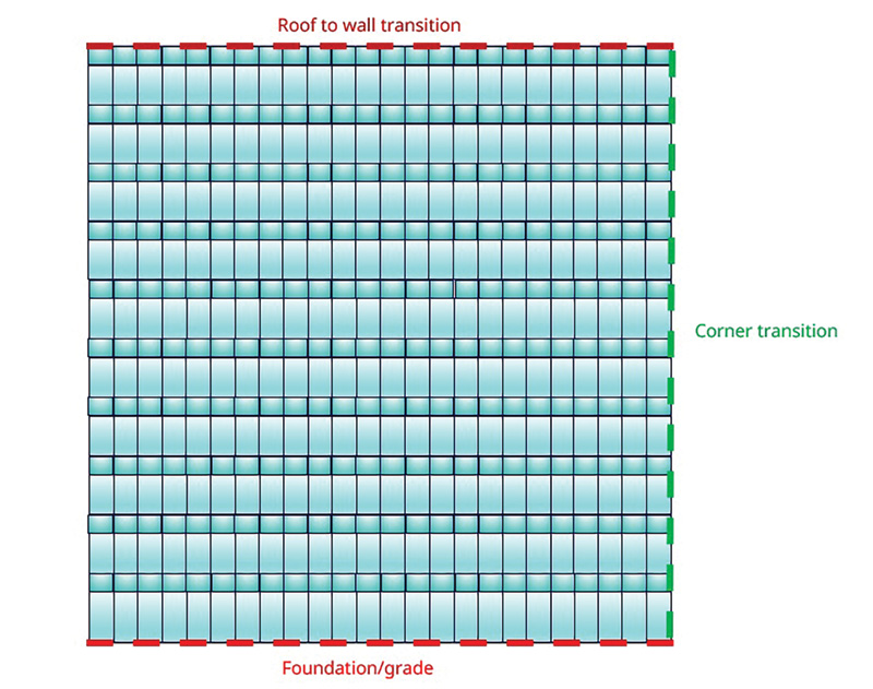
It is instructive to evaluate the impact of a fully glazed (100 percent) wall, since this minimizes wall-window transitions, and for glazed wall areas greater than 50 percent. For these, the required U-factor is relaxed to 0.91 W/m2K (0.16 BTU/hr∙sf∙F). The model facade is shown in Figure 11 and has the same dimensions as in the first example with a facade area of 1,360 m2 (14,600 sf), a 67 percent window-to-wall ratio.
For calculating the thermal transmittance, the TBG reference mitigated linear derating values listed in Figure 9 for the first example were applied to the curtain wall-to-roof, to-grade, and corner transitions. The same curtain wall system was used as in the first example for comparability.
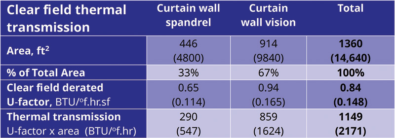
Figure 12 shows the clear field thermal transmission of the curtain wall vision and spandrel areas. As described in the first example, the spandrel U-factor has been derated for thermal bridging.
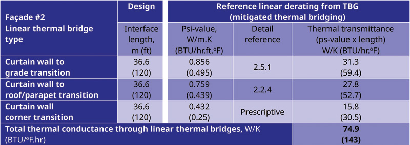
Figure 13 illustrates the thermal transmittance of the linear thermal bridging interfaces. There are no reference derating details in the TBG for curtain wall corner transitions, so the prescriptive value was used. In practice, a 3D simulation of the corner may be appropriate, especially in buildings with a lot of reticulation. Note that in this case, the linear thermal transmittance is five percent of the total heat flow through the facade. However, the total thermal transmittance of the wall is 31 percent higher than in the first example. The largest contribution to thermal bridging is in the spandrel clear field, which is accounted for in the spandrel U-factor derating.
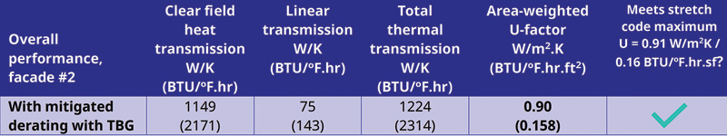
Figure 14 summarizes the total facade thermal transmittance (clear field plus linear thermal bridging) and the total area-weighted U-factor (total thermal transmission divided by the total area). The result demonstrates that the 100 percent curtain wall can comply (just) with the higher U-factor = 0.91 W/m2K (0.16 BTU/hr∙sf∙F) Massachusetts code requirement. However, it requires the vision curtain wall to have a U-factor below 0.97 W/m2K (0.17 BTU/hr∙sf∙F) and highly insulating spandrel—neither of which represents business-as-usual installed performance in the U.S.
Takeaways from facade examples
To comply with Massachusetts’ Stretch Code target and relative performance paths, especially when using glazed wall systems, designs must:
- Minimize thermal bridging at interfaces, avoiding prescriptive derating
- Use highly insulating fenestration with U-factors less than 0.97 W/m2K (0.17 BTU/hr∙sf∙F)
- Use highly insulating spandrel assemblies
- Use thermally broken cladding attachment systems
Solutions that support achieving this level of performance are illustrated below.
Solutions
Rainscreen wall systems
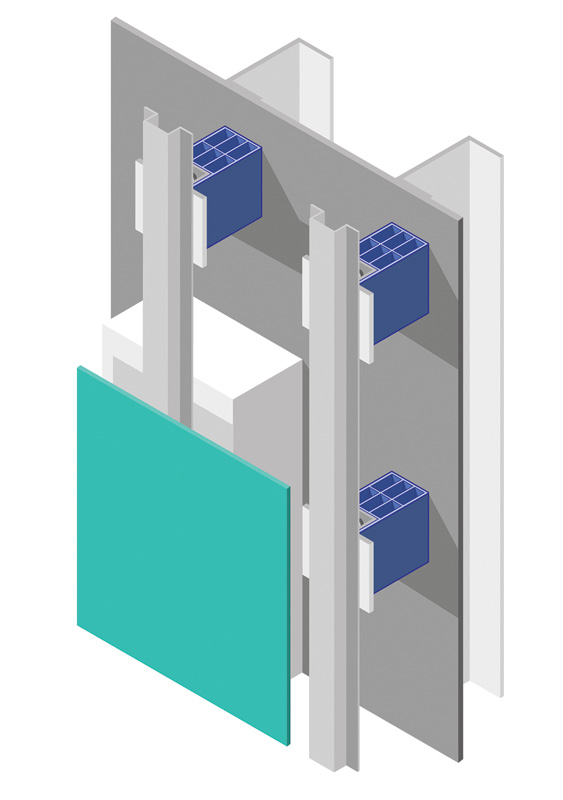
Opaque wall systems should be detailed with thick continuous insulation (c.i.) with mitigation of linear and/or point thermal bridges. Attachments should be thermally broken by using thermally broken clip point supports instead of continuous aluminum z-girts, and the frequency of attachment points should be minimized (Figure 15).
Fenestration
The prescriptive fenestration U-factors of 1.7 W/m2K (0.30 BTU/hr∙sf∙F) for fixed windows and 1.8 W/m2K (0.32 BTU/hr∙sf∙F) for operating windows, and the minimum U-factor of 1.4 W/m2K (0.25 BTU/hr∙sf∙F) for glazed wall vison areas will generally not be sufficient to meet the overall vertical wall U-value requirements when complying through the target or relative performance paths.
As indicated by the examples, vision fenestration U-values will likely need to approach 0.91 W/m2K (0.16 BTU/hr∙sf∙F) to meet the requirement and will require the following strategies:
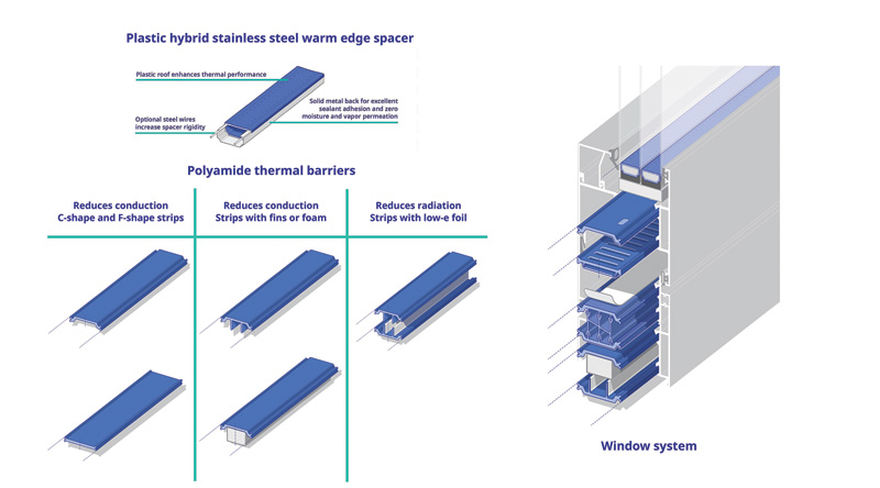
- High-performance aluminum frames with wide, complex thermal barriers that significantly reduce heat conduction and convection (Figures 7 and 16). Deep thermal breaks centered on the glazing to align the thermal insulation plane and provide an optimal solution in terms of conduction. Additional performance improvements can be realized with the addition of foam in the thermal break cavities to reduce convection and radiation heat loss. In addition, these improvements also reduce condensation risk and improve thermal comfort.
- Warm-edge spacer, such as a plastic hybrid stainless steel (PHSS) spacer (Figure 16), in the IG unit to reduce conduction at the edge of glass.
- Argon-filled, triple-pane IG unit with optimized cavity dimensions of approximately 13 mm (~0.5 in.) and two low-e coatings, one in each cavity, delivering a center-of-glass U-value of approximately 0.68 W/m2K (0.12 BTU/hr∙sf∙F). Incorporating vacuum insulated glazing (VIG) as the room-side lite of an IG unit (hybrid VIG) is another potential solution. Hybrid VIG must incorporate a warm edge spacer to address VIG’s high-edge conduction and allow for a deeper thermal break in the framing system.
Captured curtain wall
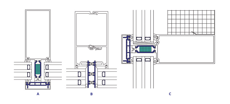
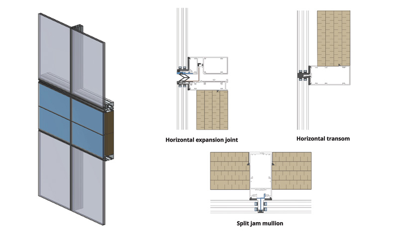
The thermal efficiency of captured curtain wall systems can be improved using deep PA dual thermal barriers to reduce conduction, foam to fill the cavities to reduce convection, and a 40 percent glass-filled PA pressure plate in place of aluminum (Figure 17a).
Structurally glazed curtain wall
For structurally glazed curtain walls, PA glass edge adapters can be used to reduce conduction and can carry gaskets, compartmentalizing cavities to reduce convective heat transfer (Figure 17b). A warm-edge spacer, such as the PHSS spacer incorporated into the detail in Figure 17b, is critical in such systems since the edge of glass is the weakest conduction link. Warm-edge spacers can reduce structurally glazed system U-factors by up to 0.28 W/m2K (0.05 BTU/hr∙sf∙F).
Spandrel assemblies
Special attention must be given to spandrel assemblies to mitigate thermal bridging. The most efficient use triple-pane glazing with warm-edge spacer, maximize the insulation behind the IG. Deep thermal barriers, foam filling, and PA pressure plates are critical tools for captured systems, as illustrated in Figure 17c.
Conclusions
To meet the aggressive envelope thermal performance targets required by the Massachusetts Stretch Code, high-performance windows, and window wall or curtain wall vision area details are required. Fenestration system U-values of 0.91 W/m2K (0.16 BTU/hr∙sf∙F) will be needed for most buildings where prescriptive compliance is not permitted, especially if glazed walls are incorporated. For these buildings, at a minimum, compliance will require high-performance triple glazing, warm-edge spacers, and well-thermally broken aluminum framing.
Curtain wall spandrel thermal performance must be maximized through optimum insulation thickness and framing details to mitigate thermal bridges.
Architectural design must mitigate thermal bridges in opaque walls and at assembly transitions. Envelope transitions, penetrations, and reticulation should be minimized to the extent possible.
Larger continuous strip windows and larger curtain wall vision modules can improve performance due to reduced fenestration-to-wall interfaces (thermal bridging) and increased glass-to-frame ratio (lower U-factor). U-factors for project-specific fenestration sizes can be used where they exceed the National Fenestration Rating Council’s (NFRC) model sizes.
Compliance on projects with glazed wall systems may be easier to achieve at glazed wall areas exceeding 50 percent as the overall vertical wall U-value required relaxes to 0.91 W/m2K (0.16 BTU/hr∙sf∙F).
Due to the increased compliance complexity, envelope system experts must be brought to the design table early—much earlier than they have historically been consulted. To achieve success, a holistic envelope design approach and early coordination across trades to manage thermal bridges at system interfaces is essential. Engaging with envelope consultants familiar with Massachusetts’ Stretch Code, and with fenestration system fabricators and installers will support creative high-performance design and solution development.
Authors

Helen Sanders, PhD, is a general manager at Technoform North America, headquartered in Twinsburg, Ohio. She has more than 25 years of experience in glass technology, market development, and manufacturing, especially in functional coatings, insulating glass, and thermal zone technology for fenestration. Sanders has a doctorate in surface science from the University of Cambridge, England. She is an active member of many industry organizations and in codes and standards development. She is the founding president and current board president of the Facade Tectonics Institute. She is also a board member of the Insulating Glass Certification Council (IGCC), the National Fenestration Rating Council (NFRC), and the Fenestration and Glazing Industry Alliance (FGIA). In addition, she serves as co-chair of FGIA’s Glass Products Council and its Innovation and Sustainability Steering Committees. She was a member of the envelope subcommittee for the 2024-International Energy Conservation Code (2024-IECC) development and is a member of the consensus committee for the 2027-IECC development. She can be reached at helen.sanders@technoform.com.

Fred Worm is a sales engineer with Technoform Insulation Solutions and a professional engineer registered in Ontario (PEO). Based in Penticton, B.C., he has more than 30 years of experience in curtain wall, skylights, and window product development, as well as product testing and installation. He assists in providing high-performance, precision extruded polyamide thermal profiles for manufacturers of metal-framed windows, doors, and other facade and fenestration systems. Providing the foundational education for his extensive career, he graduated from the University of Waterloo in Ontario with a bachelor’s in mechanical engineering. He can be reached at fred.worm@technoform.com.
Key Takeaways
Massachusetts’ Stretch Code sets a new national standard for energy efficiency by enforcing stringent requirements on building envelope performance, particularly in minimizing heating loads and thermal bridging. The code prohibits envelope trade-offs, mandates low U-factors for vertical walls and fenestration, and introduces complex compliance paths. Success requires early coordination among design, envelope, and fenestration experts. High-performance solutions—such as triple-glazed windows, thermally broken framing, and advanced spandrel assemblies—are essential for compliance, especially in glazed facades. The code emphasizes holistic thermal design and early integration of envelope strategies to meet decarbonization and energy efficiency goals through sustainable, high-performance construction.
Sign up for our weekly newsletter
Architectural materials and methods delivered right to your inbox
- CSI News & Notes: CSI’s impact earns official recognition; celebrate leaders, mentors, and innovators; and more
- CSI News and Notes: CSI spring certification exams open; scholarships available; and more
- CSI News & Notes: CSI MSR heading to San Diego; spring certification exams open; and more
- To Be Specific: Why CDT Should Be Your First Move
- CSI News & Notes: CSI Fellows share member benefits; and a New Year’s Resolution to keep
Related Products

Read the Latest Issue