Field mockups for exterior wall systems: Will the design pass the test?
Preconstruction considerations
Mockups are an essential part of any construction project, whether a complicated innovative design utilizing new materials or a simple renovation replacing materials in-kind. Even with today’s photorealistic renderings generated through building information modeling (BIM), people still want to touch, feel, and see the real thing. However, and more importantly, BIM or computer-aided design (CAD) detailing cannot resolve all of the field-dependent variables discussed above. Constructing and testing a mockup represents the last opportunity to refine the design approach before the actual fabrication of components begins and before any unresolved or unknown issues are constructed into the building.
However, while the value of the mockup process cannot be overstated, it comes with cost and schedule impacts. This means getting the most value out of a mockup is critical. Performance parameters should be further verified during the course of the project with a program of field testing, which is outside the scope of this article.
When incorporating mockups into a project, the design documents and specifications should outline the intent and requirements for the mockup. Historically, aesthetic mockups have been utilized early in the construction process for architects and owners or authorities having jurisdiction (AHJ) to approve design appearance, finish materials, and color palette. However, a project team will also include performance testing of the façade mockup components and assemblies if it is determined to be necessary. Many believe projects do not require performance mockups when the systems have previously been tested. However, even if the individual systems have been tested, a mockup may still be beneficial to establish the methods of integration between these systems and to establish the finished quality and performance of these integrations, as this is where water leakage and performance problems are frequently encountered. It is critical for team members to communicate and understand the intent of the mockup, whether aesthetic, performance, or both, early in the process to avoid differing expectations.
The designer or specifier should include requirements for the mockup, defining all tests, performance requirements, testing conditions, and qualifications for the testing agency and installers, as well as the pass/fail criteria of individual components or the assembly. Tests and pass/fail criteria may be based on previous laboratory certification testing for the various systems, building code requirements, and special project considerations such as history of severe weather at the site. Where more than one system is involved, detailing of system-specific testing at individual areas of the mockup may be warranted. The specifier should also identify the parties responsible for paying for tests and retests in case of failure. Finally, methods of resolving defects in failed assemblies may be specified if they can be anticipated.
The complexity of the enclosure design is an important consideration when developing and specifying the mockup process, as it correlates to the level of risk inherent in the design. For example, a simple rectangular building clad with standard systems and components should present minimal risk and may require less extensive field tests during installation. Similarly, the risk tolerance of the end user is an important factor. A storage warehouse may be less affected by leakage than a hospital. As a designer, it is critical to understand how to balance risk mitigation and cost when implementing performance mockup criteria.
Costs for a mockup, including design, construction, and testing costs, can vary greatly depending on the size, complexity, and testing requirements. A simple single-story metal stud, veneer construction mockup with a single water infiltration test built at the jobsite could cost as little as $25,000, while a multistory mockup in a laboratory, with multiple systems and transitions undergoing several performance tests, may cost $250,000 or more and take several months to plan, construct, and test. Both cost and time are major factors to be considered, especially in today’s fast-track construction environment. However, the mockup tests can reveal system weaknesses that can be costly and affect project performance and the schedule if not caught early, far outweighing the initial cost. Therefore, mockup construction and testing can provide assurance a custom-designed system will match the performance of other standard systems with established track records of success.
Constructing the mockup
Enclosure performance mockup testing can include structural loading, thermal cycling, and condensation resistance, but the most common tests the authors have encountered are air and water infiltration testing of fenestration and air infiltration testing of air barrier assemblies.
Air infiltration testing of fenestration products is conducted in accordance with ASTM E283, Standard Test Method for Determining Rate of Air Leakage Through Exterior Windows, Curtain Walls, and Doors Under Specified Pressure Differences Across the Specimen, or ASTM E783, Standard Test Method for Field Measurement of Air Leakage Through Installed Exterior Windows and Doors, depending on whether testing is performed in the laboratory or field.
Water infiltration testing of fenestration products is conducted in accordance with ASTM E331, Standard Test Method for Water Penetration of Exterior Windows, Skylights, Doors, and Curtain Walls by Uniform Static Air Pressure Difference, or ASTM E1105, Standard Test Method for Field Determination of Water Penetration of Installed Exterior Windows, Skylights, Doors, and Curtain Walls by Uniform or Cyclic Static Air Pressure Difference, depending on the laboratory or field conditions respectively. While all of the above-mentioned tests were developed for test of fenestrations, they are also used for opaque walls today.
For both air and water infiltration testing it is important the specifier not only include the applicable ASTM test, but also the appropriate performance and procedure requirements, and whether to test surrounding flashing conditions. A common mistake is to simply reference the product performance requirements for field testing. This can cause confusion between the specifier, manufacturer, installer, and testing agency, as both air and water infiltration laboratory testing criteria are modified to be less stringent for use in the field in accordance with AAMA 502, Voluntary Specification for Field Testing of Newly Installed Fenestration Products. For air infiltration the test pressure is the same between lab and field conditions, but AAMA 502 allows a 50 percent increase in air leakage rates from lab to field performance. Water infiltration tests conducted in the field use a one-third reduction in test differential pressure from the lab-applied pressure in accordance with AAMA 502. Both changes from lab to field conditions are required within AAMA 502 unless the specifier states otherwise. In the absence of either option being clearly defined within the specifications, the agency will typically default to the less stringent testing requirements, which include the reduced test pressure and not testing surrounding flashing conditions.
Additionally, there are two different test types for water penetration resistance. ASTM 1105 provides two test methods; procedure A is a uniform pressure test while procedure B is a cyclical test. A uniform test applies to AW class windows and cyclical tests apply to R, LC, and CW performance classes as defined by AAMA 101, Voluntary Performance Specification for Windows, Skylights, and Glass Doors. A uniform test is a one-test cycle, consisting of water spray being applied continuously for 15 minutes with the specified pressure. Cyclic tests include applications of air pressures, with each cycle consisting of constant pressure for five minutes followed by zero pressure for one minute, and then repeated four times, during which the water spray is continuously applied.
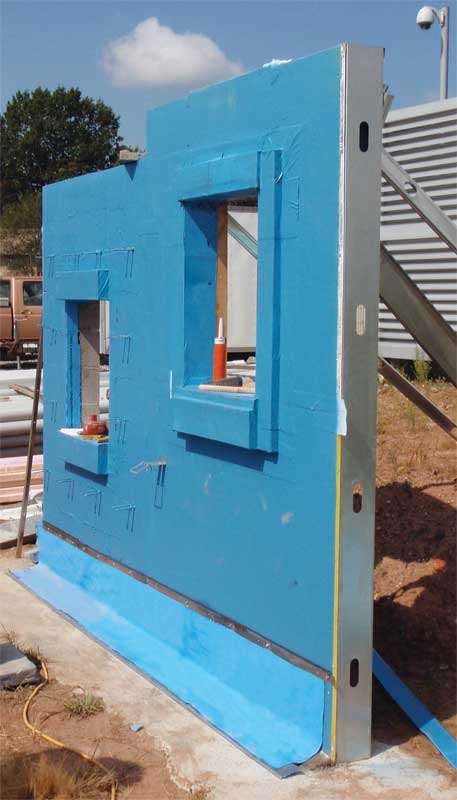
Air infiltration testing of air barrier assemblies is conducted in accordance with ASTM E2357, Standard Test Method for Determining Air Leakage of Air Barrier Assemblies, and includes testing two wall assemblies: an opaque wall and a wall with various penetrations. The opaque wall assembly is a simple stud frame wall panel, 2286 mm (90 in.) square, which includes fasteners through the sheathing, panel joints, and treatment of the joints according to the air barrier manufacturer’s instructions. The penetrations assembly includes junction boxes, pipe and duct penetrations, masonry ties, and a window in addition to the opaque panel requirements (Figure 1). Air testing of the two wall assemblies is then conducted in accordance with ASTM E283. It is important to note ASTM E2357 and ASTM E283 are both laboratory test standards not intended to be used in the field. However, in some instances, this testing has been attempted onsite. One of the major challenges in performing this test in the field is the difficulty of constructing a sufficiently airtight test chamber to exclude extraneous air leakage during the test, which may affect its validity. Therefore, this test may not be practical outside of a laboratory setting.
Sign up for our weekly newsletter
Architectural materials and methods delivered right to your inbox
- CSI News and Notes: CSI Foundation’s construction camp; CSI spring exam; and more
- CSI News and Notes: CSI’s credentials; CSI conference theme; and more
- To be specific – CSI supports young AECO professionals
- CSI News and Notes: CSI’s foundation scholarships, national conference, and Crosswalk
- CSI News and Notes: AI’s impact; CSI 2024 conference, and more
Products


Read the Latest Issue