More than one way to skin a building
Insulation and condensation control requirements
To protect the structure against condensation, Section 1405.3, “Vapor retarders,” of IBC requires the installation of vapor retarders as described by the Code or as part of an approved design using a hygrothermal analysis (the analysis may determine a vapor retarder is not necessary. The placement of the vapor barrier in both wall types requires coordination with the location and amount of insulation, dictated by Code in either a prescriptive or a performance-based approach. Similar to air and water management strategies, face- and concealed-barrier systems differ in the location and type of materials employed to achieve thermal and condensation performance requirements.
In a concealed-barrier assembly, the insulation may be placed inboard and/or outboard of the A/WRB. Conversely, insulation must be inboard of the air and water barrier in a face-barrier cladding system.
Where insulation aligns in adjacent face- and concealed-barrier walls, locating the vapor barrier (if required) is relatively straightforward. Yet, if the insulation is on opposite sides of the A/WRB, different vapor barrier locations in the wall assembly will be required.
Transitions of the A/WRB between face- and concealed-barrier walls complicate and may prevent insulation and vapor barrier continuity. In the absence of insulation or vapor barrier continuity, cold bridging or vapor bypass may occur. Combining these systems, therefore, requires evaluation at the transitions to negotiate the impact of thermal bridging or possible gaps in the vapor barrier.
Offsets and discontinuity in the A/WRB plane
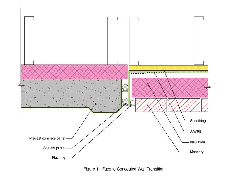
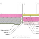
A building—for aesthetics, structural attachment, or constructability reasons—may not rely on a single wall type across the entire façade. In transitions between a face-barrier system to one with cladding outboard of a concealed barrier, the A/WRBs will be at different planes in each assembly. The detailing of these transitions can be challenging, but is crucial for maintaining the building’s overall performance. A barrier system passing ASTM E331 must include transitions in the test specimen, and the assembly’s manufacturer often has typical details to illustrate these transitions. These are a good place to start in designing these transitions. However, each system is different, and the designer must take the differing geometry and materials for each assembly into account. As face-barrier systems typically rely upon sealant joints at the perimeters, the transitions can usually be achieved by integrating flashing elements with the air barrier as substrate for the sealant joint (Figure 1).
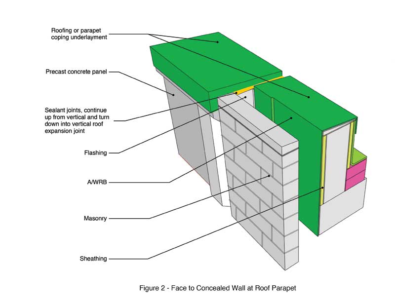
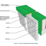
The designer must also consider transitions to other enclosure systems, including roofing, below grade, and plaza waterproofing. Figure 2 illustrates a transition from a face to concealed-barrier wall at a roof parapet.
Combined fenestration termination to face and concealed A/WRB
With fenestration, the best air- and water-resisting performance is achieved by aligning the plane of the A/WRB with the inner face of the fenestration element’s “wet zone,” which is the glazing pocket or frame element collecting and draining exterior water. The inner plane of the wet zone is just inboard of glazing pocket for curtain walls (i.e. pressure bar systems) and at the back edge of the frame for storefront and sill can fenestration; prefabricated windows with block frames are similar to storefronts unless they have a nail fin.
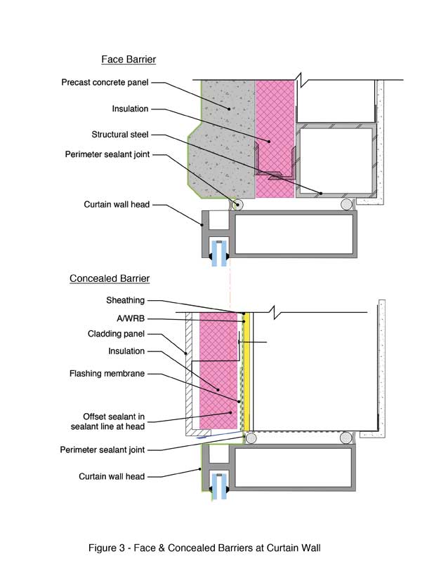
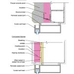
If the fenestration is surrounded solely by face- or concealed-barrier façade, the sealant joint can be set in one continuous plane. Combining the face and barrier façade elements at one fenestration creates the need to coordinate both the planes with the fenestration. This can result in the need to create an offset in the sealant joints and to accommodate the geometries of all three (Figure 3).
Structural attachment and boundary conditions
Face barrier precast concrete and GFRC must be attached to primary or relatively robust secondary structural members. It is impractical to have continuous back-up A/WRB on sheathing. While not problematic for continuous-barrier façades, transitions to the concealed ones create difficulty in coordination and tolerances between the differing systems.
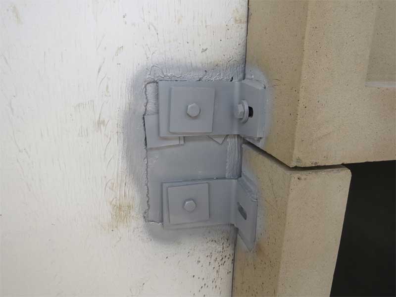
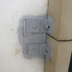
Generally if the precast/GFRC elements are installed first, the concealed A/WRB can run to and be sealed to the sides of the panels. If delays in procuring precast/GFRC occur, it will be necessary to leave the adjacent edges of concealed A/WRB incomplete so they can be installed with proper clearances to the precast. Attachment locations may, however, preclude installation of face-barrier elements following concealed barrier cladding. See Figure 4 for a jamb transition for precast to concealed A/WRB detailing with steel stud backup wall. In this example, the structural mount of the precast panels interferes with the A/WRB and possible flashing transition illustrated in Figure 1.
For concrete backup wall, it is necessary for some of the precast/GFRC attachments to protrude beyond the edges of the panel (typically the top or side “swinging” in to make the final connections). In this case, the concealed A/WRB and flashings must be custom fit around the attachments requiring field fabrication of sheet metal and flexible flashing for an airtight as well as watertight transition.

