Drawing the line on wall flashing: Identifying gaps in current practice
When waterproofing flashings are absent from buildings, there is a high risk of leaks. Water intrusion accounts for more than 70 percent of construction litigation. Delays, callbacks, and change orders can also result from omitting flashing details from the initial building design.
Sheet metal flashing has been included in construction for more than 100 years. Galvanized sheet metal (GSM) used as flashing has become a proven commodity—one so common that important characteristics for its use are missing in construction drawings, specifications, and industry references. The purpose of this article is to focus on GSM for wall-framed buildings.
Sheet metal flashing has been consistently used as a transition material between wall flashings and contemporary and traditional concealed drainage-plane water-resistant barriers (WRBs) behind claddings such as stucco, siding, and various wall cladding panel systems. Sheet metal flashing is also used to transition window and door openings to the various WRBs available on the wall.
Current practice, despite drawbacks
The construction industry and design professions have not kept pace with documented code revisions, traditional designs, flashing details, and specifications used in current practice.
This article (the first of two) will address galvanized sheet metal problems observed over many years in conjunction with wood and metal-framed low-rise buildings in the Western U.S. Sheet metal flashing detailing in today’s construction industry diverges in four ways from potential best practice:
- Non-compliance with building codes—Incomplete flashing details on drawings do not conform to current applicable building codes.
- Absent construction details—Lack of flashing detailing training for architectural schools or design office apprentices.
- Lack of industry references—Galvanized sheet metal flashing does not have a dedicated industry reference for wall-framed, low-rise buildings. They are typically found with residential and light commercial construction.
- Incomplete specifications—Current specification templates are generic, lack wall-specific flashings, and have not kept pace with available flashing material and fabrications.
These issues are important, especially now, as we examine current practices and the opportunities that have been passed over in building design, detailing, fabrication, and installation.
Building code requirements
Building codes requiring roof and wall flashings have evolved in recent years. There are additional wall flashing requirements for wall openings, such as windows, doors, and wall penetrations. Two applicable national building codes include the International Building Code (IBC)1A and the International Residential Code (IRC).1B Wall flashings are addressed in the code in three ways: specific building locations, required details on drawings submitted for permit, and newly approved flashing materials.
The importance of flashings is reemphasized with recent inclusions in the building codes. New installation requirements appeared in the 2021 IRC for window/door flashing, Sec. R703.4.2 and for water-resistive barriers, Sec. R703.7.3.
Flashing locations
Building codes list some wall locations that require flashings. Sheet metal flashings are generally required by building codes at common transitions and termination locations of walls.
The 2021 IRC Sec. R703.4 code excerpt indicates specific locations for wall flashing installations. These locations include wall flashings at windows and doors, above projecting wood trim, weep screeds, and decks attached to wood-frame construction. The IBC also identifies specific locations for flashings:
2021 IBC Section 107.2.4 Exterior Wall Envelope. “…provide details… including flashing, intersections with dissimilar materials, corners, end details, control joints intersections at roof, eaves, or parapets, means of drainage, water-resistive barrier and details around openings.”
Flashing details required on permit drawings
Critical waterproofing details required by building codes must be included on construction drawings submitted for a building permit. As noted above and below in the code excerpts, the flashing details are required on plans:
2021 IBC Section 107.2.4 Exterior Wall Envelope. “The Construction Documents shall provide details of the exterior wall envelope …”
2021 IRC Section R106.1.1 Information on Construction Documents. “… Construction documents shall be of sufficient clarity to indicate the location, nature and extent of the work proposed and show in detail that it will conform to the provisions of this code.”
Code-approved flashing materials
Sheet metal is the default corrosion-resistant flashing material specified by the codes, with a minimum thickness of 26 gauge, equal to 0.55 mm (0.0179 in.) Galvanized sheet metal is the historically common, practical, and affordable sheet metal used for roof and wall flashings to comply with building codes.
In addition to the continued use of traditional sheet metal flashings, new weatherproofing materials have been introduced to the construction industry since the 1980s. These include self-adhering flashings (SAF) and liquid-applied flashing (LAF), as well as the introduction of newer water-resistive barriers (WRB) and air barriers (AB) for framed wood and light-gauge steel residential and low-rise commercial buildings.
Regardless of code requirements, waterproofing details are often absent in architectural practice. And it is common to find incomplete drawings and specifications with flashing details or requirements omitted.
Attention to flashings is not highly emphasized in the training or practice of building department plan reviewers and field inspectors, where life-safety issues take priority. Even though flashing is emphasized in the building codes, plans without flashing details are often approved, even though the details are absent from the drawings. Part two of this article will address this. As a building is being built, the locations requiring attention are often overlooked in specifying effective flashing.
Construction drawings and details
The subject of building technology, including building waterproofing, is not emphasized in most architectural schools; therefore, the requirement and need for flashing are notably absent. The technical aspects of architectural training have been assumed to be learned in the design office from field-experienced staff. However, typical construction drawings often omit showing flashings in wall details.
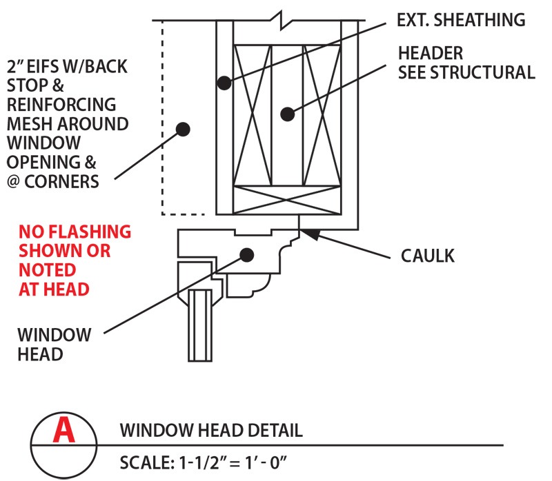
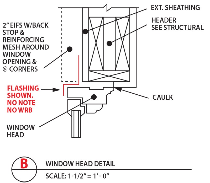
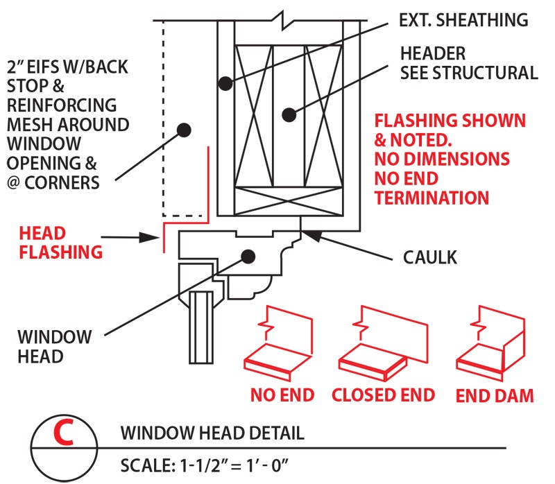
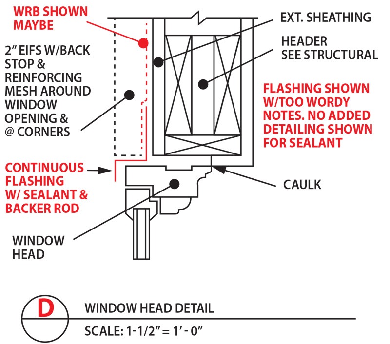
Examples of typical details with absent flashings are shown in Figures A to D. Details with the note “Flashing by Others” are not acceptable today (Figure A). Or, when flashing is shown graphically, the detail does not include drawing notes identifying flashings (Figure B). When the details with flashings are shown with drawing notes, dimensions are not included (see Figure C on page 21).
Sometimes, an over-reliance on inflated detail notes leads to components not being illustrated. See Figure D on page 21 for the transition of flashings to a WRB.
Architectural details are expected to show buildings and building assemblies in standard graphic representation, including vertical and horizontal section views, such as head, jamb, and sill for window openings. Figures A to D are representative examples of various head details that could be found on many construction drawings. However, it is rare to find 3D corner details on construction drawings. Details in 3D may appear in a fabricator’s shop drawing submittals if required by the project specifications. Current practice for bidding and shop drawing submittals has sheet metal subcontractors bid only on what is shown and noted in the details. Or, a bidder will choose the available options that best align with their intended scope of work when the construction documents are not otherwise clear. This can have unintended consequences, such as increased requests for information (RFIs),
change orders, and changes to the budget’s cost and scope.
Industry references
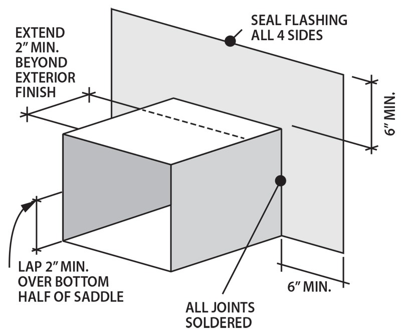
Sheet metal flashing for buildings is known in the trade as architectural sheet metal. The most widely used industry references for sheet metal flashings are publications2 from the Sheet Metal and Air Conditioning Contractors’ National Association (SMACNA). Their primary reference is the Architectural Sheet Metal Manual (ASMM), published in its present format since 1965. It is the most referenced publication in project specifications, and its two most notable benefits are the numbering of individual details and the presentation of 3D sheet metal drawings, often with sheet metal shading to enhance graphic understanding (similar to Figure 1 on page 18). However, most SMACNA details do not include 3D views of flashing corners and terminations. The SMACNA details show completed multi-piece assemblies and not the fabrication of separate flashing pieces.
The SMACNA reference for residential construction is the Residential Sheet Metal Guidelines (RSMG) published in 2001. An example of a freehand rendering of a sheet-metal flashing detail from RSMG (Figure 5-1) is shown in Figure 1.
Limitations of SMACNA references
Even though these two SMACNA references are useful and ubiquitous, they have a few limitations. First, SMACNA emphasizes roofing sheet metal, so its content predominates with masonry flashings and roofing counter flashings. Second, since its inception, the ASMM has had a U.S. East Coast bias in its masonry wall construction features. Only one of the 20-plus pages of flashing details in Chapter 4 of ASMM contains a framed wall flashing example. Third, ASMM tends to show complex and ornate sheet metal configurations, such as spires, trash chutes, and cornices, to demonstrate sheet metal’s versatility, but does not show everyday, mundane wall flashing configurations used for practical waterproofing details. These critical details impact performance and are as important as any complex, sophisticated flashing and waterproofing assembly. Fourth, it lacks discussion of contemporary sheet metal fabrication practices, such as spot welding, blind riveting, and coordinating with other flexible flashings, e.g. SAF and LAF.
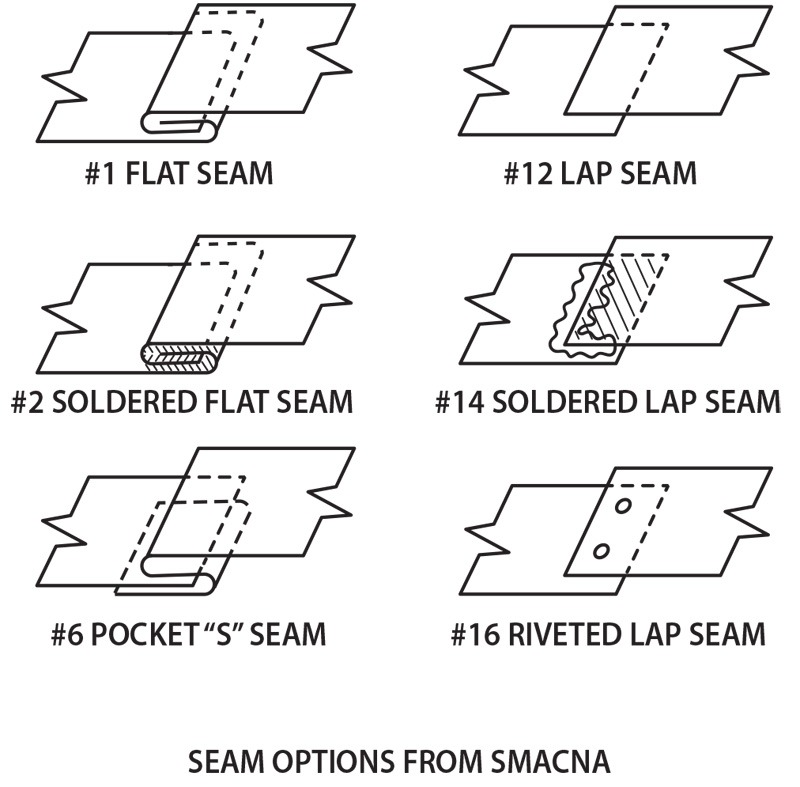
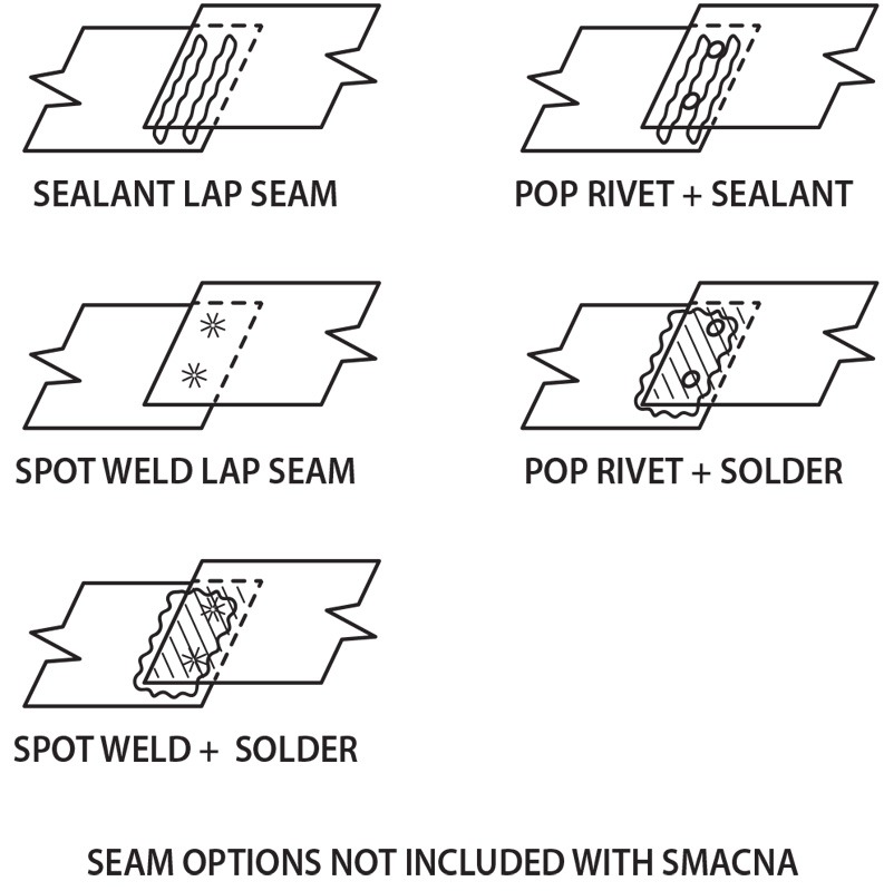
Project specifications often refer to SMACNA’s ASMM in general terms, e.g. “comply with SMACNA.” However, the ASMM may offer more options than the project specifications or drawings present. Typical specifications do not acknowledge or select available specific SMACNA details (see Figure 2 on page 22). The ASMM contains embedded options that range in performance from simple lapped and sealant seams to mechanically fastened and soldered watertight seams. Unless a specific SMACNA option is identified in the project drawings or specifications, the sheet metal bidder may select any available option for installation and still meet the minimum specification requirements. The ASMM encourages specific selection, stating, “direct reference to this manual [ASMM] by figure or detail number is encouraged.” Most specifications do not reference specific SMACNA options (see Figure 2 on page 22). But even so, not all detail options now available, reflecting contemporary practices, are included by SMACNA (see Figure 3 on page 23).
What has been lacking is an updated industry reference for designers and specifiers that focuses on wood- and metal-stud wall framing with galvanized sheet metal (see part two of this article). This type of construction has been predominantly used in the Western U.S. since the 1920s. Framed walls remain the most common structural system for residential and light commercial buildings after World War II.
SMACNA briefly covers the mechanical fastening of simple lapped galvanized sheet-metal joints using blind rivets or spot welding.
Blind rivets
SMACNA does not address fastening sheet metal by rivets in any depth, except stating, “Joints that are locked and soldered do not require rivets for additional strength. Joints that are lapped and soldered require rivets to strengthen the seam.” Most wall flashings do not use locked seam joints, so mechanical fastening joints are the recommended best practice. The fastening process with blind (“pop”) rivets (a common mechanical fastening method), followed by soldering, is not covered by SMACNA.
The blind riveting process starts with the layout of holes to be punched or drilled through lapped sheet metal, with the hole size dependent on rivet diameter, typically 3.2 mm (¹/₈ in.) Basic riveting starts with clamped pieces secured flat and tight, then a hole is drilled through both sheets with a rivet inserted. Field-drilling, where the sheet metal piece is set directly on the wall substrate, and holes are then drilled, should not be performed to avoid puncturing any pre-installed underlying flexible flashing or WRB. The blind rivet has a mandrel pin at one end that is inserted into a rivet gun. The mandrel is drawn tight and snaps inside the rivet with release. The rivet securely fastens the two sheet-metal pieces. The protruding rivet head should not penetrate any underlying flashing membrane or WRB. Performance is affected by the thickness of the metal pieces, the rivet’s depth, and the selected diameter.
Spot welding laps
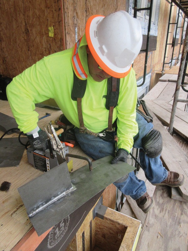
Spot welding is a type of resistance welding in which thin sheets of lapped metal are fused in a spot by pulsed electrical resistance. Spot welding with soldering is not noted in any SMACNA detail, and the combination alone is not watertight. It is a mechanical fastening process in which lapped sheet-metal edges are held together under pressure by a machine using two opposing electrodes, then welded with a burst of electric current. The variables in spot welding performance include weld time, electrode tip size, electric current, and metal thickness. Spot welding can occur in a shop or on-site with portable equipment.
Soldering seams
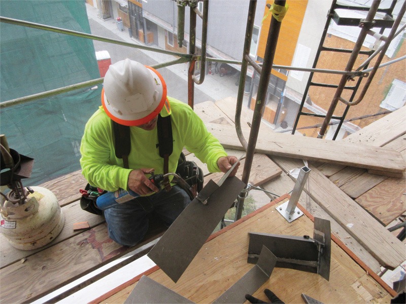
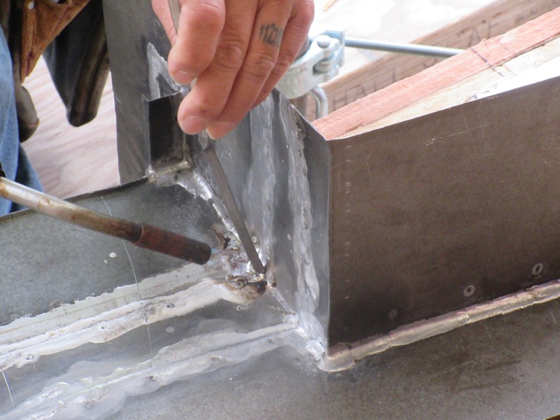
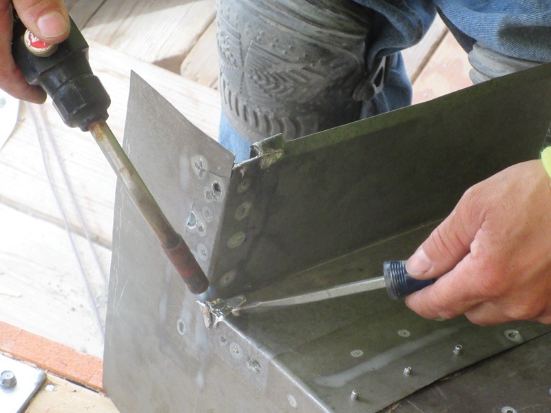
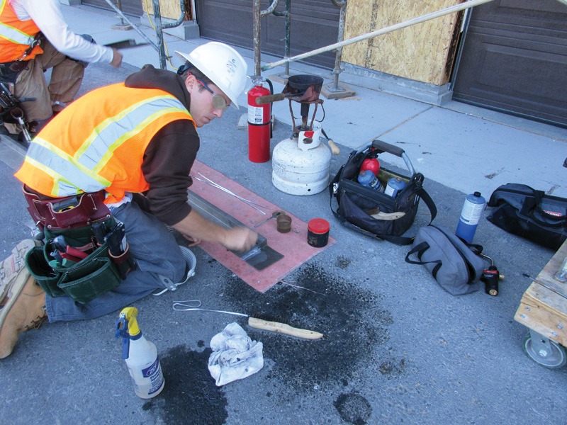
Watertight joints in lapped sheet metal can be achieved by soldering between the laps. Soldering is only superficially mentioned by SMACNA. In today’s practice, after joints are fastened with blind rivets or spot welding, the entire lapped joint is fully sweat-soldered. Galvanized sheet-metal flashings’ joints are waterproofed at the seams by soldering. Soldering must fill the lapped area and the edges. Soldering alone is not relied upon for structural strength without mechanical fastening of rivets or spot welding. Performance is affected by flux preparation, solder temperature, the width and depth of the metal lap, and the extent of fully sweated solder.
The SMACNA manuals are geared more toward sheet metal shop practice and management than design, layout, and detailing.
Guide specification templates
Specifications identify the design and construction requirements, with expected coordination with the construction drawings. Drawings and specifications are complementary, meaning they have equal precedence. Unless a different order of precedence is agreed to or specified by the policies of certain owners, e.g. some governmental agencies, both specifications and drawings are required; written specification descriptions will not take the place of omitted details on drawings.
In general, designers use only a few resources to develop sheet metal flashing specifications for a specific project, including a similar previous project, a specification consultant, a client-provided specification, and proprietary specification guides.
The accepted specification format from all sources of specification content is based on the Construction Specifications Institute’s3 (CSI) MasterFormat section 07 62 00—Sheet Metal Flashing and Trim.
CSI is the design professions and construction industry’s predominant resource for building construction specification formatting.
Project specification development usually occurs in design offices, where designers either reference a similar past project or start by editing a guide specification template. A specification template should be modified with additions or deletions to suit the current project and current practices. Guide template specs often become outdated and incomplete, especially regarding wall flashings. Many boilerplate provisions become reused without relevance to the current project.
The typical guide template for today’s 07 62 00 spec has limitations and omissions in its scope, failing to address newer methods for detailing and installing architectural sheet metal flashings. Typical 07 62 00 specs, such as SMACNA, focus on roof flashings and sheet metal accessories. There is little separate attention to wall flashings on framed buildings as a format section in typical sheet metal specifications.
Therefore, it is not surprising to find sheet metal installers ignoring vague and outdated project specifications. Bidders encountering missing or incomplete details will only bid on what is shown and noted on the drawings. Including bids for absent flashings risks non-competitive bids (too high to win a contract). The successful low bidder can later submit change orders for any added or missing flashings. It is no longer acceptable for specification resources to include omnibus specifications that broadly require the work to be completed to the satisfaction of the architect, without specifying whether all necessary elements have been identified, worked out by the designer, and documented.
The following items are excerpts from a typical 07 62 00 example guide specification, followed by the author’s commentary:
System Description: The requirements shown by details are intended to establish basic dimensions, profiles and sightlines. Within these limitations, the Contractor will be responsible for the design of sheet metal flashing and trim assemblies and make whatever modifications of and additions to the details as may be required to prevent water and air penetration.
Author’s commentary: This is an example of a rather vague specification transferring design decisions from the designer to the contractor. It is also a retrograde omnibus specification that imposes an overall burden on the contractor to complete the installation, without requiring the designer to spell out a comprehensive scope of work and detailed specifications.
This broad language can result in, for example, the sheet metal installer submitting and installing a product that does not meet the intended design performance. Since galvanized sheet metal flashing is a commodity item, flashings are sourced from regional steel mills, stockpiled by metal distributors, and fabricated on demand in individual regionally based shops. There is no expectation of written instructions from the individual steel mills that produce galvanized sheet metal. Individual fabricators or local sheet metal shops may have their own accepted practices, but these likely vary and are not available during the project design phase. Product consistency will not occur without specific details and specification requirements in the construction documents. Architects do not have access to documentation of individual shop practices during wall design unless project files were retained as references from a previous building project.
2.0 Products – Rivets: High-strength aluminum or stainless-steel rivets suitable for metal being fastened where necessary for strength.
Author’s commentary: “Where necessary” leaves the decision up to the sheet metal installer’s judgment. This phrase does not conform to CSI’s style guide4 and provides an ambiguous direction with no qualitative requirements for measuring performance. These installation practices differences vary from shop to shop and do not appear until shop drawings are submitted.
3.0 Installation General: Install sheet metal flashing and trim to comply with performance requirements, SMACNA’s “Architectural Sheet Metal Manual” or as indicated.
Author’s commentary: This is a general reference to an industry publication that offers several options. It is so vague that, if the specifications intend to support the general design intent but do not require specific ASMM details, there may be no available wall flashing detail in the ASMM for the building locations noted for flashing. Further, SMACNA does not classify its details by performance rating. The phrase “or as indicated” is currently found in most guide specification templates. The phrase “as indicated” is generally presumed to mean as shown on the drawings. If the drawing details are incomplete, however, this reference to a specification catch-all phrase becomes pointless.
3.0 Installation Riveting: Install rivets for strength where needed for strength.
Author’s commentary: “Needed for strength” is a vague requirement. This phrase does not conform to CSI’s style guide4 and could be interpreted as a performance specification, but without any test requirement. Generally, this corresponds to the extent of rivet requirements outlined in most guide specification templates.
These are just a few representative examples of specification sections that should be revised (refer to part two of this article). Galvanized sheet metal wall flashing should be treated in more detail and with more comprehensive specifications at present, with changes based on the author’s limited review of current practices. This current research has reviewed example specification templates and selected representative project manuals. Today’s specification guides for section 07 62 00 exhibit a common repetition of spec format, product subjects covered, installation, and spec language.
Conclusion
Several metal types are used for flashings in building construction, including galvanized sheet metal, copper, stainless steel, zinc, and lead. Each metal material has its own differing features to account for in detailing, fabrication, and installation.
Building designers, due to a lack of teaching in school or training in the design office, are insufficiently knowledgeable about flashing detailing. This results in missing flashing details in construction documents. Secondly, when details are incomplete, the construction documents will not comply with building code permit submission requirements. Thirdly, no industry reference is available for sheet metal flashing in wall-framed buildings. Lastly, the current generic specification templates have not kept up with today’s available flashing fabrications. Completed sheet metal flashing design and construction requires addressing these four factors.
The four factors of improved detailing, designer training, more options, and generic specifications for sheet metal flashing for framed wall buildings can converge to meet current best practices with attention to simple changes. With specific guidance on the design and detailing of sheet metal flashings, architects, building designers, specifiers, fabricators, and quality control inspectors should be able to develop a comprehensive reference to better evaluate expected performance. With a dedicated sheet metal wall flashing reference, subcontractor bids will estimate the same scope of work and will not be left to select the least costly available SMACNA option.
The construction industry and design professions’ use of computer modeling with building information modeling (BIM), computer-aided design (CAD), and 3D software offers opportunities not only to make shop drawings and fabrications more efficient, but also to increase the development and widespread use of 3D architectural detailing.
Notes
1 Refer to International Code Council, (A) International Building Code (IBC), 2021; and (B) International Residential Code (IRC), 2021, iccsafe.org.
2 Read more at Sheet Metal and Air Conditioning Contractors’ National Association (SMACNA), (A) Architectural Sheet Metal Manual (ASMM), 2012;
and (B) Residential Sheet Metal Guidelines (RSMG),
2001, smacna.org
3 See Construction Specifications Institute (CSI), MasterFormat, 2020; and Construction Specifications Practice Guide (Alexandria, Va.: Construction Specifications Institute, 2018), 41, csiresources.org.
Author

Robert Bateman, NCARB, is a licensed architect in California and a registered architect in Washington and Nevada. He has more than 35 years of experience practicing as a forensic consultant, investigating building leaks, developing construction repair details, and conducting construction document peer reviews for new projects. He has developed flashing sequence details for manufacturers’ instructions for adhered-veneer and SAF for framed wall buildings. Besides contributing to the standards ASTM E2112 and E2266, he has written two guidebooks for window installations and stucco details, available at flashingdetails.com. He welcomes sheet metal flashing detail suggestions for a forthcoming sheet metal flashing guide and can be reached at jrobert.bateman@gmail.com.
Sign up for our weekly newsletter
Architectural materials and methods delivered right to your inbox

- CSI News & Notes: CSI’s impact earns official recognition; celebrate leaders, mentors, and innovators; and more
- CSI News and Notes: CSI spring certification exams open; scholarships available; and more
- CSI News & Notes: CSI MSR heading to San Diego; spring certification exams open; and more
- To Be Specific: Why CDT Should Be Your First Move
- CSI News & Notes: CSI Fellows share member benefits; and a New Year’s Resolution to keep
Related Products

Read the Latest Issue